


.
68.
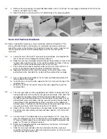
Install 2-3/4" main wheels on the aluminum landing gear using the hardware as shown on the plans. A drop of CA on the
inner nut will help keep the assembly from vibrating loose. Once the wheels have been attached, the landing gear
assembly can be bolted to the fuselage using three 6-32x1/2" mounting bolts.
NOTE: Optional wheel pants can be installed as shown in the diagram to help spruce up the appearance of your model.
Use SIGSH378 plastic wheel pants (not included in kit) painted to match your color scheme.
69.
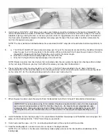
a. If you wish to install a pilot, now is the time to do it. Be sure to glue it firmly so it won't come loose in flight.
b. Cut the excess plastic away from the canopy using scissors. Cut to the mold line around the front and at the sharp
corner around the back. Sand the rough edges smooth being careful not to scratch the clear plastic.
c. Trial fit the canopy to the fuselage and trim if necessary for a good fit. Position it so that the raised frame ends at
the rear tips of the top deck and tape it down at a couple of spots.
d. Our canopies have all been attached just using 1/4" striping tape applied half to the canopy and half to the covering
material around the canopy, with good results. This allows you to easily remove and replace the canopy if ever
necessary. Finish off the canopy with 1/4" striping tape applied to the raised frame and at the back edge.
NOTE: The back edge of the canopy should only touch the three fuselage
stringers when installed properly. However, we have found that after many flights,
the back edge will begin to cut through the covering material at those spots, due
to vibration. To avoid this chafing problem, apply a spot of CA or silicone rubber
sealant (available at hardware stores) at each of the stringers where the canopy
makes contact.
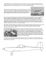
The remaining sections of these instructions concern engine and fuel tank
installation, radio installation, pre-flight checkout, and flying provide information
that is specific to the FOUR-STAR 40. For a more indepth look at any of these
subjects, please refer to "The Basics of Radio Control" booklet also included with
this kit. In particular, it is strongly recommended that you go through the "Pre-
Flight Checklist" in Chapter 7 carefully before attempting to fly.
Engine And Fuel Tank Installation
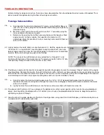
Engine installation on the FOUR-STAR 40 is simply a matter of bolting the engine mounts that were prepared in step 28 to
F-1, then bolting your engine to the mounts. Finish installing the throttle cable (which was partially prepared in step 51) by
soldering the connector in place on the servo end of the cable.
Like most Sig kits, the fuel tank in this model is installed from the rear of the fuel tank compartment rather than through a
removable hatch. This choice was made for several reasons. A hatch opening makes the nose weaker and it's very difficult
to keep oil from leaking in around a hatch. A method of fastening the hatch must be built into the fuselage, adding to the
complexity and construction time. Besides, modern plastic fuel tanks are virtually fMestructible under normal use when
installed properly, so they seldom need to be removed for maintenance.
An 8 ounce fuel tank is recommended for the FOUR-STAR 40, although most
tanks from 6 oz. to 10 oz. will work. A Sullivan Products 8 oz. Slant Type, RST
Type, or Round Type will fit easily, as will an 8 oz. Du-Bro tank. A 10 oz. Sullivan
tank (RST, Slant, or Round Type) or a 10 oz. Du-Bro tank will require some
modifications (widening) to the opening in F-2. Most engines will require the tank
to mounted as high as possible in the fuselage. Use foam rubber under the fuel
tank as necessary to position it properly.
Radio Installation
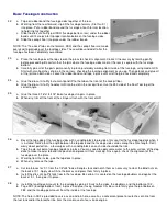
Screw the nylon control horns onto the rudder and elevator as shown on the plans, then re-install the inner nylon push
rods that you prepared in step 49. Snap an R/C link on the rudder horn, then cut off the excess nylon tubing, leaving a 1/8"
gap between the end of the tubing and the R/C link. Cut a 2-56x10" threaded rod to an overall length of 3-1/4", measuring
from the threaded end. Install the threaded rod in the nylon tubing, smooth end first, so that approximately 1/2" of the
threaded portion remains exposed. (The metal rod will help prevent the nylon tubing from buckling under flight loads.)
Thread the R/C link onto the end of the push rod until the rudder is neutral, then repeat the procedure for the elevator.
The aileron servo can be mounted to short lengths of hardwood as can be seen on the W-1 cross section on the plans.
Содержание Four-Star 40 SIGRC44
Страница 1: ......