background image


TSX1D200MTS                                                                                                         V1 FEB13   

- 20 - 


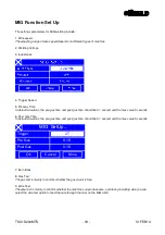
MIG  SetUp

 Burn Back

  Gas   Test

  Wire Test

Medium 1

OFF

OFF

Ok

Cancel


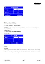
TIG Function Set Up 
 

The settings parameters for TIG welding include: 
 
1. Current 

Upon adjustment of the welding current, the voltage will change, however you are unable to change the 
voltage independently. 

 
2. Welding Voltage 

The voltage is unable to be changed independently.


3. Down Slope Time 


4. Trigger 
 
5. Pre Gas 

In default situations, the pre-gas time and post-gas time should be 0.1 second and the max value 5 seconds. 

6. Post Gas Time 

In default situations, the pre-gas time and post-gas time should be 0.1 second and the max value 5 seconds. 


Содержание MTS 200

Страница 1: ...MTS 200 User Manual SWMTS001 TSX1D200MTS ...

Страница 2: ...design EN60974 1 Arc welding equipment Part 1 Welding power sources Additional information restrictive use Class A equipment intended for use in locations other than residential By signing this document the undersigned declares as manufacturer or the manufacturer s authorised representative established within the EEA that the equipment in question complies with the safety requirements stated above...

Страница 3: ... Installation 5 OPERATION 5 1 Connection and Control Devices 5 2 Display Function Diagram 5 3 Operating Functions 5 4 MIG Function Set Up 5 5 TIG Function Set Up 5 6 MMA Function Set Up 6 RECOMMENDED WELD PARAMETERS 7 DAILY CHECKLIST ROUTINE MAINTENANCE 8 PARTS LIST CIRCUIT DIAGRAM 9 FAULT TRACING TROUBLESHOOTING 10 ACCESSORIES ...

Страница 4: ...tion Ask for your employer s safety practices which should be based on manufactures hazard data ELECTRIC SHOCK Can Kill Install and earth the unit in accordance with application standards Do not touch live electrical parts or electrodes with bare skin wet gloves or wet clothing Insulate yourself from earth and the workplace Ensure your working stance is safe FUMES AND GASES Can be dangerous to hea...

Страница 5: ...ting signal on the front panel shall activate and light up In this instance do not unplug the machine however allow the fan to cool the machine to the required temperature to start welding again Current overload will reduce the service life and could result in damage of the machine and even burning out of the thermal inverter Mains Input Supply Refer to the Recommended Weld Parameters within this ...

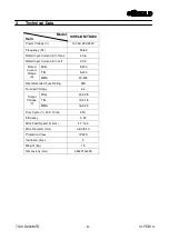
Страница 6: ...nput Current A I 1eff 20 3 MIG 5 200 TIG 5 200 Rated Current Range A MMA 30 200 Recommended Fuse Rating 32A No Load Voltage 63 MIG 20 2 28 TIG 10 2 18 Output Voltage V MMA 16 5 24 Duty Cycle 40 C 10min 25 Efficiency 0 73 Wire Feed Speed m mm 2 7 14 4 Wire Diameter mm 0 6 0 8 1 0 Protection Class IP23S Insulation Class F Weight Kg 15 Dimensions mm 439x214x405 ...

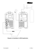
Страница 7: ...nimise voltage drop Prior to installation check the following Confirm both air vents are no covered obstructed or blocked otherwise this could result in failure of the cooling system Ensure the machine is connected to a suitable grounded mains supply Installation for MIG Applications 1 Connect to a suitable cylinder with required regulator and gas hose 2 Select desired polarity via the quick conne...

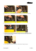
Страница 8: ...pressure arm 6 Feed the wire into the guide tube and through the wire feed roll Set the correct pressure on the arm and fit back into place Ensure that the pressure is enough to hold the wire in place however not too much as this will deform the wire 7 Insert the MIG gun onto the front of the machine and feed the wire through into the gun ...

Страница 9: ...TSX1D200MTS V1 FEB13 9 Diagram for Installation for MIG Applications ...

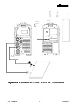
Страница 10: ...with required regulator and gas hose 2 Select desired polarity via the quick connect sockets on the front of the machine 3 Select the Spool on Gun function via the switch inside the machine Plug the spool on torch into the front of the machine 4 Insert the control plug into the silver control plug socket ...

Страница 11: ...pen the spool gun and mount the wire spool onto the spindle 6 Secure the spool with the retaining screw 7 Feed wire into the guide tube 8 Release the pressure of the feed rolls and feed the wire through into the tip of the torch ...

Страница 12: ...TSX1D200MTS V1 FEB13 12 Diagram for Installation for Spool On Gun MIG Applications ...

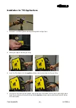
Страница 13: ...ptor onto the gas fitting 3 Insert the TIG adaptor into the negative polarity socket and screw onto the gas fitting 4 Connect the TIG torch into the adaptor and connect the control cable into the silver control plug socket Insert the control plug of the earth clamp into the positive polarity socket and connect the earth clamp to the work piece ...

Страница 14: ...TSX1D200MTS V1 FEB13 14 Diagram for Installation for TIG Applications ...

Страница 15: ... Insert the earth clamp control plug into the desired polarity socket for application The SifWeld MTS200 machine allows for two welding modes DC and DC In DC positive applications ensure the electrode holder is connected to the positive polarity socket In DC negative applications ensure the electrode holder is connected to the negative polarity socket ...

Страница 16: ...TSX1D200MTS V1 FEB13 16 Diagram for Installation for MMA Applications ...

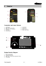
Страница 17: ...2 MCP Mono Control Point 7 Input Hose 3 Welding Current Connectors 8 Mains Switch 4 Euro Block 9 Mains Input Cable 5 Control Socket Display Function Diagram 1 Mains Supply Switch 2 Overheating Indicator 3 MCP Mono Control Point Adjustment Knob 4 LCD Display 2 1 3 4 2 1 7 3 4 5 6 8 9 WELD MTS200 ...

Страница 18: ...e weld parameters settings interface using the MCP Mono Control Point adjustment knob by rotating it left or right to select the parameter you wish to edit Select the parameter by pressing the MCP knob and adjust as necessary pressing the knob again to save your setting You can set other parameters under each function mode by using the More button to view further settings If you wish to save your ...

Страница 19: ...1 second and the max value 5 seconds 6 Post Gas Time In default situations the pre gas time and post gas time should be 0 1 second and the max value 5 seconds 2T MIG SetUp Trigger Pre Gas Post Gas 0 1S 0 1S Ok Cancel More 7 Burn Back 8 Gas Test The gas test is mainly to confirm whether the gas circuit is free 9 Wire Test The wire test is mainly to confirm whether the machine can produce wire and d...

Страница 20: ...voltage will change however you are unable to change the voltage independently 2 Welding Voltage The voltage is unable to be changed independently 3 Down Slope Time 4 Trigger 5 Pre Gas In default situations the pre gas time and post gas time should be 0 1 second and the max value 5 seconds 6 Post Gas Time In default situations the pre gas time and post gas time should be 0 1 second and the max val...

Страница 21: ...ent Upon adjustment of the welding current the voltage will change however you are unable to change the voltage independently 2 Voltage The voltage is unable to be changed independently 3 Arc Force The size of the Arc force will be changed with the current and it gets from the percentage of present welding current setting value MMA SetUp Current Voltage ARC Force 10A 20 4V 0 ...

Страница 22: ...TSX1D200MTS V1 FEB13 22 4 Hot Start ...

Страница 23: ...23 30 40 10 15 20 25 1 0 8 70 80 17 18 50 60 10 10 15 1 2 1 0 85 90 18 19 50 60 10 10 15 1 6 1 0 100 110 19 20 50 60 10 10 15 2 1 0 115 125 19 20 50 60 10 10 15 2 4 1 0 130 140 20 21 50 60 10 10 15 3 2 1 0 150 170 21 22 45 50 15 15 20 Normal Welding Speed 4 5 1 0 140 200 22 24 45 50 15 15 20 1 0 8 140 19 20 160 10 15 1 2 0 8 130 150 19 20 120 10 15 T Joint High Welding Speed 1 6 1 0 180 22 23 120 ...

Страница 24: ...aking or buzzing sound 2 When power is on check for peculiar smell Power Section 3 Check for overheating by any colour change on the unit 1 Check whether the gas pipeline is damaged or the connection is loose Periphery 1 Check the outer shell and other parts are not loose Welding Gun Section To Check Note 1 Whether this is securely fitted Nozzle 2 Clear of spatter 1 Whether this is securely fitted...

Страница 25: ...ure Roll 1 Check the pressure roll rotates freely and does not pressurise the wire This can result in damaging the wire if the pressure is too high Cables Section To Check Note 1 Ensure the welding gun cable is not over bent Welding Gun Cable 2 Ensure the connections of the quick plug are in good condition 1 Check the insulation is in good condition Welding Cable 2 Check the fittings and that ther...

Страница 26: ...nsuring you use the correct air pressure to avoid damaging the machine Check the internal electrical connections are in good condition reinforcing any loose parts If there is any corrosion within the internal electrical connections remove this as required and reconnect Do not use the welder in damp or wet conditions If the welder is not used for a prolonged period put this in the original packagin...

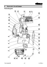
Страница 27: ...TSX1D200MTS V1 FEB13 27 8 Parts List Circuit Diagram Parts Diagram ...

Страница 28: ...ctromagnetic value 21 Radiator 6 Retifier bridge 22 Plastic support bar 7 Sheet metal clapboard 23 B3 Europe joint 8 Plastic handle 24 Nylon foot pad 9 PCB control panel 25 Plastic baseboard 10 IGBT 26 Wire feeder 11 PCB panel 27 Sheet metal clapboard case 12 Liquid crystal display 28 Hinge 13 Plastic front panel 29 Sheet metal carthweel board 14 Sheet metal panel 30 Plastic gate lock 15 Knob 31 P...

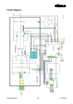
Страница 29: ...TSX1D200MTS V1 FEB13 29 Circuit Diagram ...

Страница 30: ...ptions before attempting to repair the unit This table can be found on the next page WARNING The following operations require the operator to have competent electrical knowledge comprehensive safety knowledge and hold the required qualification to repair this unit If in doubt please contact the Weldability Sif Technical Department on 0870 330 7757 Fault Solution Display light is not on the fan doe...

Страница 31: ...hall be able to resume welding If neither of the above options work then it would seem that the inverter is damaged therefore please contact Weldability Sif Technical department on 0870 330 7757 If the unit is still not working after you have checked all options please contact the Weldability Sif Technical Department on 0870 330 7757 Check points maintenance items Fault No arc No gas No wire feed ...

Страница 32: ... Welding Gun Cable Torch consumables are not damaged and are correct for the application Contact tip nozzle and nozzle joint are secure Welding Gun Torch fitting is not too tight or loose Cables are not broken Gun Power Cable Switch Control Cable Cables are not damaged Clean from oil dirt rust and paint Material surface wire length Wire does not need cutting back Good earth connection Output Cable...

Страница 33: ...stage two gauge Argon regulator TWN001COMP Gas Input Hose Mini MIG Hose FXMT2003 SifGun MIG 200A 3m Euro MIG Gun TSX1D200SOG Spool on MIG Gun 4m Spool on Gun accommodates D 100 spools FXTT092645 SifGun TIG 4m TIG Gun with rocker switch FXADF2012 SifLite Olympian ADF 9 13 auto darkening welding helmet DZ10012 Inverter Trolley Black inverter trolley ET001W MIG Helper Pliers Multi functional MIG plie...

Отзывы: