Page 1/44
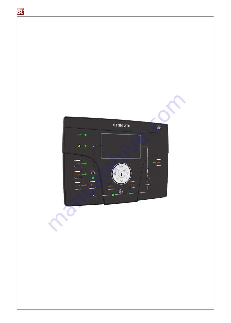
GENSET CONTROLLER
Automatic Transfer Switch
Instruction Manual
ST 301 ATS
Страница 1: ...Page 1 44 GENSET CONTROLLER Automatic Transfer Switch Instruction Manual ST 301 ATS ...
Страница 2: ...2 1 Navigation chart Global Setup 15 2 2 Navigation instructions 16 2 3 M1 Mains setup 17 2 4 M2 Alternator setup 18 2 5 M3 Engine setup 19 2 6 M4 General setup 20 2 6 1 M4 1 Display setup 20 2 6 2 M4 2 Clock setup 20 2 6 3 M4 3 Test setup 21 2 6 4 M4 4 Security setup 22 2 7 M5 Alarms list 23 2 7 1 M5 Alarms default parameters 24 2 7 2 M5 Alarms description 25 2 8 M6 Special functions 26 2 8 1 M6 ...
Страница 3: ...owledge but no liabilities for errors omissions or contingencies arising there from are accepted A circuit breaker must be included in the electrical installation of the building It must be installed close by the equipment and within easy reach of the operator It must be marked as the disconnecting device of the equipment IEC EN 61010 1 6 12 2 1 Clean the instrument with a soft dry cloth do not us...
Страница 4: ...terface type Serial RS485 Baud rate Up to 115200 bps CONTACTORS RELAYS N outputs 2 Type of contacts 1x N O genset contactor 1x N C mains contactor Contatcs capacity 8 A 250 VAC LOAD CURRENTS INPUT N 3 Measure range Up to 5A VOLTAGE INPUTS N 8 Input type Resistive coupling Rated voltage 230 Vac L N 400 Vac L L Measure range TRMS from 0 to 300 Vac L N from 0 to 500 Vac L L ACTIVE POWER MEASURE Measu...
Страница 5: ...Page 5 44 1 4 Electrical Installations 1 4 1 Drawing Warning Before inserting the plugs and supply the board make sure that the connections strictly comply with the wiring diagram below ...
Страница 6: ...put default Faulty start 5 6 Not used 5 7 Not used 5 8 Programmable output default Global alarm 1 5 9 Programmable output default Auto mode 5 10 Programmable output default Manual mode 5 11 Programmable output default Siren RS232 Communication ports RS232 connection of a remote device J8 RS485 port 1 Shield 2 A 3 B 4 Termination resistor J3 Genset AC current 3 1 Genset current I1 3 2 Genset curren...
Страница 7: ... and the remote start output is deactivated If the cause of the alarm remains the cause is still present Push the RESET button to select this functioning mode 1 5 4 Test mode Manual test Press the TEST button the remote start output is activated to test the genset for a programmable time a If activated during MAN mode the load switching can be controlled only by KG and KR buttons even if the mains...
Страница 8: ...anual mode If it s pressed and released quickly it deactivates the output after the cooling time if it s pressed for 3 seconds it deactivates the output immediately In manual test mode this button permits to manage the mains contactor K MAN Button to select the manual mode L Navigation drive Navigation drive composed by 4 arrows to scroll through the pages left and right arrows and increase or dec...
Страница 9: ...pages you can go to the status and alarm page Here you can see the organization diagram of the display pages Notes Pages Mains 1 2 3 4 are shown only if parameter M in menu M1 is set to Three phase Pages Genset 1 2 3 4 are shown only if parameter M in menu M2 is set to Three phase Page Engine is shown only if the communication with genset is enabled inside menu M7 1 START DOWN ARROW Logo ON 5 sec ...
Страница 10: ...If the vertical cursor is available on display it s possible to use up and down arrow buttons to see more pages for the section in this case from the mains measure 1 to mains measure 2 With up arrow button you can return to the previous page of the section Inside the main page there is also the horizontal cursor which means that the left and right arrow buttons are available When the controller is...
Страница 11: ... 1 7 3 4 Mains 3 shown only in case of 3 phase system A Mains apparent power L1 L2 L3 and total B Mains active power L1 L2 L3 and total C Power factor L1 L2 L3 and total 1 7 3 5 Mains 4 shown only in case of 3 phase system A Mains apparent power L1 L2 L3 and total B Mains reactive power L1 L2 L3 and total C Power factor L1 L2 L3 and total 1 7 3 6 Mains control kWh A Total active energy supplied by...
Страница 12: ...ours left to service D Oil pressure E Engine temperature F Fuel level percentage Note this page is shown only if parameter B inside menu M7 1 is set to Modbus Master and parameter I is set to On 1 7 6 Display pages Hours A Total work hours of the generator B Total work hours with KG closed and load 0 C Total work hours with KR closed and load 0 1 7 7 Display pages Events log The events log page sh...
Страница 13: ... of the expansion board only with expansion enabled 1 7 8 5 Data info This page contains the the information about the release file REL Project release version FW Firmware release version SW TE Utilities release version DA Release date 1 7 9 Clock and warranty A Clock date and time B Controller warranty expiry date detected automatically by controller after 2 hours with mains voltage and frequency ...
Страница 14: ...e ATS with a genset controller via RS485 This way it s possible to read the most important measures and alarms directly by the ATS controller and command the starting and stopping of the genset via RS485 without other external connections The connection can be done following the drawing ...
Страница 15: ...Clock setup M4 3 Test setup M4 4 Setup Security Alarm category setup M7 1 Serial port setup M7 2 GSM setup M8 1 Input setup M8 2 Output setup M8 3 Input type M8 4 Output type M8 5 Calibrations M8 6 Expansion M6 1 EJP setup M6 2 Start by mains kW M6 3 Dummy load M6 4 Setup TPS M6 5 Hour counters M7 3 Datalogger Directly to parameters ...
Страница 16: ...up E Alarms setup F Special functions G Connectivity H I O setup If the HELP symbol is present it means that there is at least one alarm active Pressing the HELP button you directly go to the active alarms page With the arrows you can select the menu Once selected the desired menu press the i button to confirm and enter or press menu to return to the previous screen Then you will see a screen for t...
Страница 17: ... OK It is the delay time after which if the mains returns within the limits set see parameters B C E F it s considered stable and the mains contactor is closed then begins the stop phase of the generator in automatic mode 0 600 s 10 I Faulty mains It is the delay time after which the mains is considered faulty compared with the limits specified in parameters B C E F This parameter is used to filter ...
Страница 18: ...an set a delay time for closing the generator contactor This time starts from when the Genset opens the mains contactor software interlock function 0 100 s 1 K GE Ok delay It is the delay time over which if the voltage and frequency are within limits parameters B C E F the generator is considered stable and its contactor is closed 0 65535 s 5 L CT ratio It sets the ratio of Current Transformers to...
Страница 19: ...ime to cool down without load It works only in automatic mode 0 255 s 1 C Siren time It is the duration time of the acoustic advisor in case of alarm if a programmable output is set for Siren 0 1000 s 20 NOTES To avoid any incompatibility between the timings of the ATS and the controller for engine protection remember that the ON alarm delay must be at least 5 seconds higher than the preheat time ...
Страница 20: ...gs of the language only if the default option is selected IT EN FR Custom Default Default EN B Contrast To set the display contrast preferred for the Genset 0 15 10 C Show warranty If On the automatic controller warranty time will be shown on display otherwise it will remain hidden Off On On D Show IO If On the IO monitor pages will be shown on display otherwise they will remain hidden Off On On 2 6...
Страница 21: ...topped and the test finishes automatically On Off Off POS NAME DESCRIPTION Sunday If the tick is present it enables the daily test on Sunday If the tick is removed on this day the test is not executed Monday If the tick is present it enables the daily test on Monday If the tick is removed on this day the test is not executed Tuesday If the tick is present it enables the daily test on Tuesday If the ...
Страница 22: ...cked If you enter a wrong code the menu is locked until the correct code will be inserted 60 E Genset password Enter the password that locks unlocks the alternator setup and the relative alarms If you enter the code correctly to 50 the alternator setup is completely unlocked If you enter a wrong code the menu is locked 50 F Engine password Enter the password that locks unlocks the engine setup and...
Страница 23: ...ways Run Disabled E Delay Before the activation of the alarm the cause must remain present for this time 0 255 s F Retentive Choose if the alarm must be retentive ON the alarm indication remains on display until you press the reset button even if the cause has disappeared or not OFF the alarm indications disappears when the cause disappears Off On G Action Select the action in consequence of the ac...
Страница 24: ...38 User alarm 3 þ 3 21 Generator 20062 GE low voltage 5 22 Generator 20063 GE high voltage 5 23 Generator 20064 Electrical trip 2 24 Generator 20065 Load breaker open 1 25 Generator 20066 GE protection 2 26 Engine 20015 Stop engine failure 1 27 Engine 20058 Start failure 10 28 Engine 20067 Master com error 10 29 Engine 20068 Temperature alarm 0 30 Engine 20069 Oil alarm 0 31 Engine 20070 Battery a...
Страница 25: ...at is present when the digital input programmed as user alarm 3 is active M8 21 20062 GE low voltage Voltage values are under the programmed limits M2 C 22 20063 GE high voltage Voltage values are over the programmed limits M2 B 23 20064 Electrical trip Alarm that indicates that the relative digital input is active M8 24 20065 Load breaker open Alarm that indicates that the relative digital input ...
Страница 26: ...n mains side POS NAME DESCRIPTION RANGE OF VALUES DEFAULT SETTINGS A EJP enable If ON the function is enabled if OFF the function is disabled On Off Off B Start delay It is the delay time that elapses when you close to negative the terminal programmed as remote start before the generator starting 0 999 s 5 C KG delay It is the delay time that elapses after the starting of the generator if parameter ...
Страница 27: ...alculated from the rated voltage the rated current the rated power factor 0 8 and the type of the system selected 2 8 3 M6 3 Dummy load Function that allows to activate one of the programmable outputs according to the maximum and minimum thresholds programmable on load consumption If the load consumption is lower than the DUMMY ON for a period of time longer then the ON DELAY the board activates a...
Страница 28: ...e tick is removed on this day the TPS is not executed Tuesday If the tick is present it enables the TPS on Tuesday If the tick is removed on this day the TPS is not executed Wednesday If the tick is present it enables the TPS on Wednesday If the tick is removed on this day the TPS is not executed Thursday If the tick is present it enables the TPS on Thursday If the tick is removed on this day the ...
Страница 29: ...nection with RI6010 expansion and Genset Slave module for Dual standby mode Modbus slave used for remote monitoring via serial cable or Dual standby connection with a master modbus device GSM modem used to connect GSM modem None Modbus Master Modbus Slave Gsm modem Modbus Slave E RS232 baud rate Communication speed in bit per second for RS232 port 9600 115200 bps 115200 F Activate USB Confirm to ac...
Страница 30: ...rn If enabled the activation of this condition will trigger a SMS info message On Off Off Off J Remote stop If enabled the activation of this condition will trigger a SMS info message On Off On K 1 2 3 Pw char 1 2 3 Set the 6 characters password code for SMS commands if password is different from 0 0 0 0 0 0 every SMS command received without the correct password code will be discarded The syntax to se...
Страница 31: ...ntactors OFF Z 00 Z Engine temperature 3 Engine temperature if connected to a genset controller E0 E Input I4 4 status 1 Status of input I4 4 0 not active 1 active 0 Input I4 5 status 1 Status of input I4 5 0 not active 1 active 0 Input I4 6 status 1 Status of input I4 6 0 not active 1 active 0 Input I4 7 status 1 Status of input I4 7 0 not active 1 active A0 A output O5 8 status 1 Status of outpu...
Страница 32: ...fy A wrong setting could compromise the functioning of the machine SET GSM NUMBER SET Position_number Cellphone_number Position_number value is numeric between 1 6 cellphone_number is a telephone number which allows the remote device to know where SMS need to be sent For instance to set number 339 333 9000 in position 3 of remote device the sent text will be SET3 3393339000 Set the telephone numbe...
Страница 33: ...Hz Mains voltage L1 n V Mains voltage L2 n V Mains voltage L3 n V Mains frequency Hz Load current L1 A Load current L2 A Load current L3 A Total active power kW Total apparent power kVA Total reactive power kVAR Total power factor PF Battery voltage Vdc Shutdown alarm Global alarm Last alarm ID C Memory status If Ok the memory is not full if Full you can select it to erase memory Ok ...
Страница 34: ...nditions which would start the engine as faulty mains or remote start It s possible to disable remote stop during normal test or TPS test Same as parameter A I4 7 D Ground protection Ground protection alarm from digital contact Same as parameter A I4 5 E Feedback KG Feedback generator contactor Is activated if KG output is On but feedback is not and viceversa Same as parameter A None F Feedback KR...
Страница 35: ...put is used to command an indication when an alarm set as general alarm 3 appears The output remains active until you reset or the alarm disappears KG active indicates that the generator contactor is closed KR active indicates that the mains contactor is closed Alarm A the output is active when the alarm assigned to A position by M8 2 g parameter is active Alarm B the output is active when the ala...
Страница 36: ...arm 1 Mains low freq 2 Mains high freq 3 Mains low voltage 4 Mains high voltage 5 Mains v asymmetry 6 Faulty mains 7 KR feedback 8 Mains phase seq 9 Ge low freq 10 Ge high freq 11 Ge low voltage 12 Ge high voltage 13 Ge phase seq 14 Ge short circuit 15 Ge Imax 16 Ge v asymmetry 17 Ground protection 18 Emergency stop 19 KG feedback 20 User alarm1 21 User alarm2 22 User alarm3 23 Start failure 24 32...
Страница 37: ...O the output is digital type normally open Digital NC the output is digital type normally closed POS NAME RANGE OF VALUES DEFAULT SETTINGS A O5 8 Disabled Digital NO Digital NC Digital NO B O5 9 Disabled Digital NO Digital NC Digital NO C O5 10 Disabled Digital NO Digital NC Digital NO D O5 11 Disabled Digital NO Digital NC Digital NO E O5 4 Disabled Digital NO Digital NC Digital NO F O5 5 Disable...
Страница 38: ... parameter is active Alarm B the output is active when the alarm assigned to B position by M8 2 h parameter is active Alarm C the output is active when the alarm assigned to C position by M8 2 i parameter is active Start failure indicates that the generator is not detected running after the starting procedure Electrical trip the output is activated if the Electrical trip alarm is active GE ready t...
Страница 39: ...e desired speed of communication and parameter A that is the address of the device If you are using more than one device be sure that all of them have a different address If you are using the RS232 port check that parameter E is set to Modbus Slave Then set parameter F to the desired speed of communication and parameter A that is the address of the device 2 11 3 Modbus command available It s possib...
Страница 40: ... DT_NUMERIC 40655 R 1 Not used Not used DT_NUMERIC 40656 R 1 Battery voltage Battery voltage DT_NUMERIC 40657 R 10 Not used Not used DT_NUMERIC 40658 R 1 Work hours Work hours DT_NUMERIC 40659 R 1 Not used Not used DT_NUMERIC 40660 R 1 Not used Not used DT_NUMERIC 40661 R 1 Test mode on Test mode on DT_NUMERIC 40662 R 1 IO status Bit0 Input 4 4 Bit1 Input 4 5 Bit2 Input 4 6 Bit3 Input 4 7 Bit4 Inp...
Страница 41: ...s v asymmetry Bit5 Faulty mains Bit6 KR feedback Bit7 Mains phase seq Bit8 Ge low freq Bit9 Ge high freq Bit10 Ge low voltage Bit11 Ge high voltage Bit12 Ge phase seq Bit13 Ge short circuit Bit14 Ge Imax BIt15 Ge v asymmetry Status of alarms 0 alarm not active 1 alarm active DT_NUMERIC 40756 R Bin Alarm package 2 Bit0 Ground protection Bit1 Emergency stop Bit2 KG feedback Bit3 User alarm1 Bit4 Use...
Страница 42: ...35 R Flag Ge low voltage Ge low voltage DT_NUMERIC 41936 R Flag Ge high voltage Ge high voltage DT_NUMERIC 41937 R Flag Ge phase seq Ge phase seq DT_NUMERIC 41938 R Flag Ge short circuit Ge short circuit DT_NUMERIC 41939 R Flag Ge Imax Ge Imax DT_NUMERIC 41940 R Flag Ge v asymmetry Ge v asymmetry DT_NUMERIC 41941 R Flag Ground protection Ground protection DT_NUMERIC 41942 R Flag Emergency stop Eme...
Страница 43: ...larm DT_NUMERIC 41989 R Flag Last alarm ID Last alarm ID DT_NUMERIC 42054 R Dec Var Name COMMANDS Description Var Visual ID R W Scale Manual mode Manual mode DT_NUMERIC 40539 W 1 Auto mode Auto mode DT_NUMERIC 40544 W 1 Reset mode Reset mode DT_NUMERIC 40549 W 1 Start engine Start engine DT_NUMERIC 40554 W 1 Stop engine Stop engine DT_NUMERIC 40559 W 1 Test mode Test mode DT_NUMERIC 40564 W 1 KG c...