21
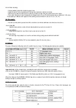
FIG. 9
Safety Instructions for Repairs
1. Safety regulations require that during a repair:
- The set should be connected to the mains via an isolating
transformer.
- Safety components, indicated by the symbol should be
replaced by components identical to the original ones
- When replacing the CRT, safety goggles must be worn.
2.
Safety regulations require also that after a repair:
- The set should be returned in its original condition.
-
T
he cabinet should be checked for defects to avoid touching, by
the customer, of inner parts.
- The insulation of the mains lead should be checked for external
damage.
- The mains lead strain relief should be checked onits function
- The cableform and EHT cable are routed correctly and fixed with
the mounted cable clamps in order to avoid touching of the CRT,
hot components or heat sinks
- The electrical resistance between mains plug and the secondary
side is checked. This check can be done as follows:
·
Unplug the mains cord and connect a wire tween the two pins
of the mains plug.
·
Switch on the TV with the main switch.
·
Measure the resistance value between the pins of the mains
plug and the metal shielding of the tuner or the aerial
connection on the set. The reading should be between 4.5 M
and 12 M.
·
Switch off the TV and remove the wire between the two pins of
the mains plug.
·
Thermally loaded solder joints should be oldered.
-This includes components like LOT, the line utput transistor, fly-
back capacitor.
Maintenance Instructions
It is recommended to have a maintenance inspection carried out
periodically by a qualified service employee.
The interval depends on the usage conditions.
- When the set is used in a living room the recommended interval
is 3 to 5 years. When the set is used in the kitchen or garage this
interval is 1 year.
- During the maintenance inspection the above mentioned "safety
instructions for repair" should be caried out. The power supply
and deflection circuitry on the chassis, the CRT panel and the
neck of the CRT should be cleaned.
9. Safety instructions, maintenance instructions,
warning and notes
!
Warnings
1
.
In order to prevent damage to IC's and transistors any flash-over of
the EHT should be avoided. To prevent damage to the picture tube
the method, indicated in Fig. 9, has to be applied to discharge
the picture tube.
Make use of an EHT probe and a universal meter is 0V (after approx
30s).
2. ESD.
All IC's and many other semi-conductors are sensitive to electrostatic
discharges (ESD). Careless handing during repair can reduce life
drastically. When repairing, make sure that you are connected with
the same potential as the mass of the set via wrist wrap with
resistance. Keep components and tools on the same potential.
3. Proceed with care when testing the EHT section and the picture
tube.
4. Never replace any modules or any other parts while the set is
switched on.
5. Use plastic instead of metal alignment tools. This will prevent any
short circuits and the danger of a circuit becoming unstable.
6. Upon a repair of a transistor or an IC assembly (e.g. a transistor or
IC with heatsink and spring) remounting should be carried out in
the following order:
1. Mount transistor or IC on heatsink with spring.
2. Resolder the joints.
Notes
1. After replacing the microcomputer first solder the shielding before
testing the set. This is needed as the shielding is used for earth
connection. If this is not done the set can switch into protection
mode (see description of the SMPS).
2. Do not use heatsink as earth reference.
3. The direct voltages and waveforms should be measured relative to
the nearest earthing point on the printed circuit board.
4. Voltages and oscillograms in the power supply section have been
measured for both normal operation ( ) and in the stand-by
mode ( ). As an input signal a colour bar pattern has been used.
5. The picTure tube PWB has printed spark gaps. Each spark gap is
connected between and electrode of the picture tube and the
Aguadog coating.
Содержание CTS-AA
Страница 1: ...CHASSIS CTS AA SERVICE MANUAL SERVICE MANUAL ...
Страница 5: ...4 Oscillograms 5 ...
Страница 6: ...5 PRINT BOARD LAYOUT 6 ...
Страница 12: ...STV2248 STV2246 Figure 7 1 TV Processor block diagram ...
Страница 24: ...23 11 2 Electromechanical CTS AA CHASIS 11 REPLACEMENT PARTS LIST CTS AA CHASIS 11 1 Electrical TABLE11 ...


