4
Fig. 3.1
For the main carrier two service positions are possible (3.1).
A: For faultfinding on the component side of the main carrier
.
B: For (de) soldering activities on the copper side of the main carrier.
Position A can be reached by first removing the mains cord from it's fixation, then loosen the carrier lips (1) and then pulling the
carrier panel (2) for approximately 10cm.
Position B can be reached from position A after disconnecting the degaussing cable. Put the carrier on the line transformer side.
3. Mechanical instructions
Содержание CTS-AA
Страница 1: ...CHASSIS CTS AA SERVICE MANUAL SERVICE MANUAL ...
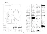
Страница 5: ...4 Oscillograms 5 ...
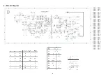
Страница 6: ...5 PRINT BOARD LAYOUT 6 ...
Страница 12: ...STV2248 STV2246 Figure 7 1 TV Processor block diagram ...
Страница 24: ...23 11 2 Electromechanical CTS AA CHASIS 11 REPLACEMENT PARTS LIST CTS AA CHASIS 11 1 Electrical TABLE11 ...


