18
8.- ELECTRICAL ADJUSTMENTS
8.1 Service mode
The signal processor IC7015 (STV2246 or STV2248) is fully controlled by I2C for the µC IC7600, so that the most of
adjustments of the set can be made by service menu.
- Enter in Service mode: There are 2 ways to enter in Service mode
- By a short circuit between pin 7 of microcontroller ( IC7600 ) and ground while the set is starting up. In this case
all controls (volume, contrast, brightness and saturation) are pre-adjusted to the mid position.
- When the set is in program 75, by pressing at the same time OSD key (+) on RC and MENU key on local key
board during 4 seconds.
Service mode is indicated by a S symbol on the down left corner of the screen.
- Display Service Menu : When the set is in service mode it is possible to display Service Menu by OSD key (+) on
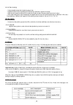
RC. Using P+, P- keys of remote control the different items can be displayed (see table 8.1):
Table 8.1. Service menu. Settings are hexadecimal values
- Pre setting values: When E2PROM is replaced, pre-setting values indicated on table 8.1 are stored by the µC. (see
8.7 E2PROM).
- Adjust by Service Mode: When a item is selected, using V+, V- keys of remote control it can be adjusted. Items 5,
16 and 17 have fixed values = pre setting values, rest of items see 8.2 to 8.7.
- Remove service menu: There are 2 ways to remove service menu
- Saving the new settings: Using OSD (+), MENU or INSTALL keys on RC.
- Keeping the old settings: Switching the TV to stand by. Service mode continues active.
- Remove Service Mode: Switching off the TV (be careful to disconnect pin 7 of microcontroller of ground)
8.2 Power supply and focusing:
- Power supply voltage:
- Adjust brightness and contrast controls at minimum.
- Connect a DC voltmeter across C2530 (Diagram D).
- Adjust R3518 for a required voltage depending on the model and the TRC used ( see table 11, page 23).
- Focusing:
- Adjust with the potentiometer placed on the line output transformer.
Содержание CTS-AA
Страница 1: ...CHASSIS CTS AA SERVICE MANUAL SERVICE MANUAL ...
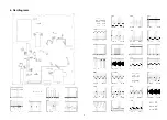
Страница 5: ...4 Oscillograms 5 ...
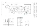
Страница 6: ...5 PRINT BOARD LAYOUT 6 ...
Страница 12: ...STV2248 STV2246 Figure 7 1 TV Processor block diagram ...
Страница 24: ...23 11 2 Electromechanical CTS AA CHASIS 11 REPLACEMENT PARTS LIST CTS AA CHASIS 11 1 Electrical TABLE11 ...

