17
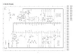
7.6 MICROCONTROLLER/TEXT (Diagram E)
The CTS-AA chassis is designed to accept 2 different microcontrollers: SAA5531 for TXT models and SAA5541 for no
TXT.
Both microcontrollers are mounted in the same position (7600), and the associated circuitry is the same. The ROM of the
ICs contain an specific program that assures all the functions of the appliance, including 2 menus, one to control the set
(see Instructions Manual) and another for Service Mode (see Service Instruct. chapter 8.1).
The µC for TXT sets contains a teletext decoder, including the following functions: TXT on/off, reveal, freeze, temporary
cancellation, clock, subcode, zoom, index, flof, page +/-, X/26 and 8/30 packet decoding (station identification and start-
up page).
Following there is an explanation of the different functions of the microcontroller indicating pins number assigned:
- Tuning (pins 1, 9): The unit has a VST (Voltage Synthesized Tuning) system. This system works by tuning to a station
on the tuner through a linear variation of the tuning voltage (V-VARI) from 0V to 33V applied on pin 2 of the tuner. It is
generated on pin 1 of the µC and converted to an adequate level for the tuner using T7605.
While searching, µC are always reading AFC (Automatic Frequency Control) and video identification signals from IC7015
by I2C bus. When video signal is identified, µc stops searching and do a fine tuning to reach a right AFC value.
- Factory facility (pin5): This pin used only in the factory should be connected to +5V by R3621.
- Service (pin 7): This pin is used to put the set in Service Mode (see chapter 8.1).
- INT/EXT input (pin 8): The set can switch to external (AV on the screen) by remote control (selecting program 0) or by
rise edge at pin 8 of euroconnector (see diagram C). The µC switches video and audio (see 5.1.2) to external via I2C bus.
In both cases the user can switch to internal changing the channel.
- Control key (pin 10): Pin 10 is activated by a DC voltage. When control keys are not activated, a voltage of 3V3 is
produced by divider R3618 and R3619. If a control key is activated, a resistor (R3665, R3667) are connected in parallel
with R3619, decreasing the voltage of pin 10. There are 3 voltage levels depending on value of parallel resistor: 1.85V
(910R + 470R), 1V (470R) or 0V (ground circuit).
- Band switching (pin 14, 15, 16): There are 3 outputs for band switching pin 15 for VHFI, pin 16 for VHFIII and pin 14 for
UHF. The µc controls the channel band in the tuner by a voltage of +5V at the correspondent output.
- L/L´ out-put (pin 18): This signal are only used on multistandard units for switching the system in sound filter (see 5.1.5).
L/L’ output is high for L’ system.
- LED (pin 19): The LED (D6663) lights up with a low current when the television set is ON and with a high current when
the set is on Standby. While the set is receiving a remote control signal, the led is blinking.
- Signal I2C bus (pins 20,21): This is a communication bus between the µc and the signal IC (7015).
Picture and sound controls: User controls (brightness, contrast, colour, sharpness and volume) are processed by the µc
and sent to IC7015 by I2C bus. The µc also sends a sound mute when the signal received is interrupted (including
channel search) and a video mute during a change of program.
- Video input (pin 23): CVBS TXT input are only used on TXT sets. The teletext information is extracted from the video
signal inserted on pins 23.
- Standby (pin 30): When this output is low, the set is switched to stand by. Signal voltages of power supply (+5V, +8V
diagram D) are reduced and the line oscillator stops, so there is no signal in pin 48 of IC7015 (diagram A).
- Power supply (pins 31, 39, 44): The IC has s3V3 power supplies, analog (pin 31), core (pin 39), and POR
periphery ( pin 44 ). All supplies are present during stand by.
- OSD outputs( pins 32, 33, 34, 35): The RGB and fast blanking outputs used for On-Screen Display (OSD) and also for
TXT are applied to RGB inputs of IC7015 (pins 34, 35, 36, 37 diagram A).
- OSD synchronization (pins 36, 37): In order to synchronize the OSD and the TXT information with the picture signal, the
VERT FLYBACK signal (pin 37) and HOR FLYBACK signal (pin 36) are added in inverted form to the integrated circuit.
Due to this if the video signal is lost, the TXT keeps synchronism.
- Oscillator (pins 41, 42): A 12-MHz oscillator is determined by a 12-MHz crystal (1679) between pins 41 and 42.
- P.O.R. (pin 43): Power on reset (POR) is activated when the set is switched on. If the µC shows abnormal behaviour it
is advisable to reset it switching off/on the set. Reset can be produced also connecting pin 43 to +5V for an instant.
- RC5 (pin 45): The commands transmitted by the remote control handset are received by infrared receiver (1685) and
passed to the microcontroller for decoding.
- Mute output (pin 46): This pin is a 3 state output used to control the sound amplifier (see chapter 7.4):
-Stand by mode (Vpin46=0V): T7657 and T7659 are cut, mute signal is 11V
-Mute mode (pin46=open): T7659 conducts (by resistor divider), T7657 are cut, mute is 5,5V.
-Operating mode (Vpin46=3V3): Both transistors conduct, mute signal is 0V.
- EEPROM (pins 49 and 50): The microcontroller is connected to non-volatile memory IC7685 (EEPROM) via bus I2C.
The following information are stored in the memory:
- Channel data including tuning voltage and band of all the channels.
- Personal preferences (PP), menu mix and child lock on user menu.
- All settings included on Service Menu.
Содержание CTS-AA
Страница 1: ...CHASSIS CTS AA SERVICE MANUAL SERVICE MANUAL ...
Страница 5: ...4 Oscillograms 5 ...
Страница 6: ...5 PRINT BOARD LAYOUT 6 ...
Страница 12: ...STV2248 STV2246 Figure 7 1 TV Processor block diagram ...
Страница 24: ...23 11 2 Electromechanical CTS AA CHASIS 11 REPLACEMENT PARTS LIST CTS AA CHASIS 11 1 Electrical TABLE11 ...


