12
7.- CIRCUIT DESCRIPTION
7.1 SMALL SIGNAL PROCESSING (Diagram A)
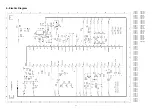
The small signal is processed by IC 7015 (STV2246 for Pal sets, STV2248 for Pal/Secam sets), including IF detection,
video processing, chroma decoder, RGB , sync processor and sound decoder. The ICs STV2246 and STV2248 are fully
controlled by I2C bus and their block diagram can see in fig. 7.1.
7.1.1 IF detection
IF detection can be intercarrier (no multistandard sets), that means sound and picture are detected in the same circuit
(PIF), or QSS (Quasi Split Sound, used in multistandard sets) where sound is detected in a separated circuit (SIF).
- PIF input (pins 6, 7): The IF signal coming from pin 11 of the tuner (diagram C) is filtered by the IF SAW filter (1015) and
applied to PIF input of IC7015 (pins 6 and 7). The IF bandpass characteristic is determined by the SAW (Surface
Acoustic Wave) filter.
- PIF oscillator (pins 9, 15, 16): The PIF PLL (phase locked loop) is based on a LC resonator (L5040). Carrier frequency
should be adjusted by I2C bus at 38.9 MHz (see chap. 8.3). A filter for the PLL is present at pin 9 (2028, 2029, 3028).
AFC is internally controlled for the µC (7600 diagram E) by I2C. Identification signal is also internal.
- AGC (pins 5, 8): The IF AGC time constant is fixed by the capacitor 2025 (pin 5). The AGC delayed voltage (pin 8) is
applied to pin 1 of the tuner and adjusted by I2C (see chap. 8.4).
- Video output (pin 13) : This baseband CVBS signal with 2Vpp of nominal amplitude, contains the FM intercarrier sound
signal. Sound is filtered out by a ceramic trap (1032 or 1033) which frequency can be different depending on the system:
5.5 MHz for BG, 6.0 MHz for I or 6,5 MHz for DK.
Multistandard sets
- The IC STV2248 is used in multistandard sets.
- Only picture IF is processed in PIF circuit (pins 6,7), and carrier frequency has a second adjustment (by I2C) at
33.9MHz for L’ standard (see chap. 8.3). The IC changes automatically between negative (BGIDK) and positive
(LL’) modulation.
- Sound IF is processed in SIF circuit (QSS system)
- SIF input (pins 1, 2): Sound is filtered from IF signal in a SAW filter K9650 (1137). The IF input is present at pin
1 of 1137 and pin 2 is used as a switching input:
- If Vpin2 = 0V a 40.40MHz sound carrier is filtered (for L´ system, L/L´ signal is high, T7127 conducts).
- If Vpin2 = Vpin1 a 33.40MHz sound carrier is filtered (for L,I,BG systems, L/L´ signal is low, T7127 is cut,
D6115 conducts).
- SIF AGC (pin 3): The sound IF AGC time constant is fixed by the capacitor C2024.
7.1.2 Sound processor
- FM demodulation: For intercarrier sets (no multistandard) FM sound is filtered internally from CVBS (pin 13) and
demodulated. De-emphasis is also made internally. If the set is Pal/Secam BG or DK, STV2248 is used instead of
STV2246. SIF input and AM demodulator are avoided and pins 1, 2 are AC grounded by C2115.
- Scart audio out (pin 11): The signal at this pin is drived to the euroconnector sound outputs (see Diagram C).
- External audio in (pin 14): External audio proceeding of pins 2,6 of euroconnector is applied to this pin. Selection
between internal or external is done by an internal switching controlled by I2C (see INT/EXT, chapter 7.6).
- Audio out (pin 55): After a volume control (by I2C), this output is drived to the input IN+ of the final sound amplifier IC7187
(Diagram C).
Multistandard sets:
FM demodulation: This function is done in the same internal circuit of STV2248 that no multi sets, but the input
proceeds of SIF circuit, instead of CVBS signal.
AM demodulation: In Multistandard sets, also AM demodulation for LL’ systems is necessary. AM sound is
extracted directly from the SIF inputs by an internal circuit.
AM/FM switch : This internal switch is commanded by the µC depending on the system selected on the tuning
menu.
7.1.3 Video processing
- Video switches (pins 18, 20, 44): The internal CVBS signal is now fed to pin 18 IC7015. External CVBS proceeding
from pin 20 of Euroconnector is present on pin 20 of 7015. The IC switches between internal and external by I2C bus (see
INT/EXT, chapter 7.6). At pin 44 there is an output of CVBS used for the TXT decoder.
Содержание CTS-AA
Страница 1: ...CHASSIS CTS AA SERVICE MANUAL SERVICE MANUAL ...
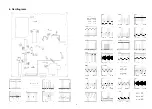
Страница 5: ...4 Oscillograms 5 ...
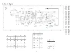
Страница 6: ...5 PRINT BOARD LAYOUT 6 ...
Страница 12: ...STV2248 STV2246 Figure 7 1 TV Processor block diagram ...
Страница 24: ...23 11 2 Electromechanical CTS AA CHASIS 11 REPLACEMENT PARTS LIST CTS AA CHASIS 11 1 Electrical TABLE11 ...


