


05.91
6 NC Channel/PLC Interface (DB 10 ... DB 25)
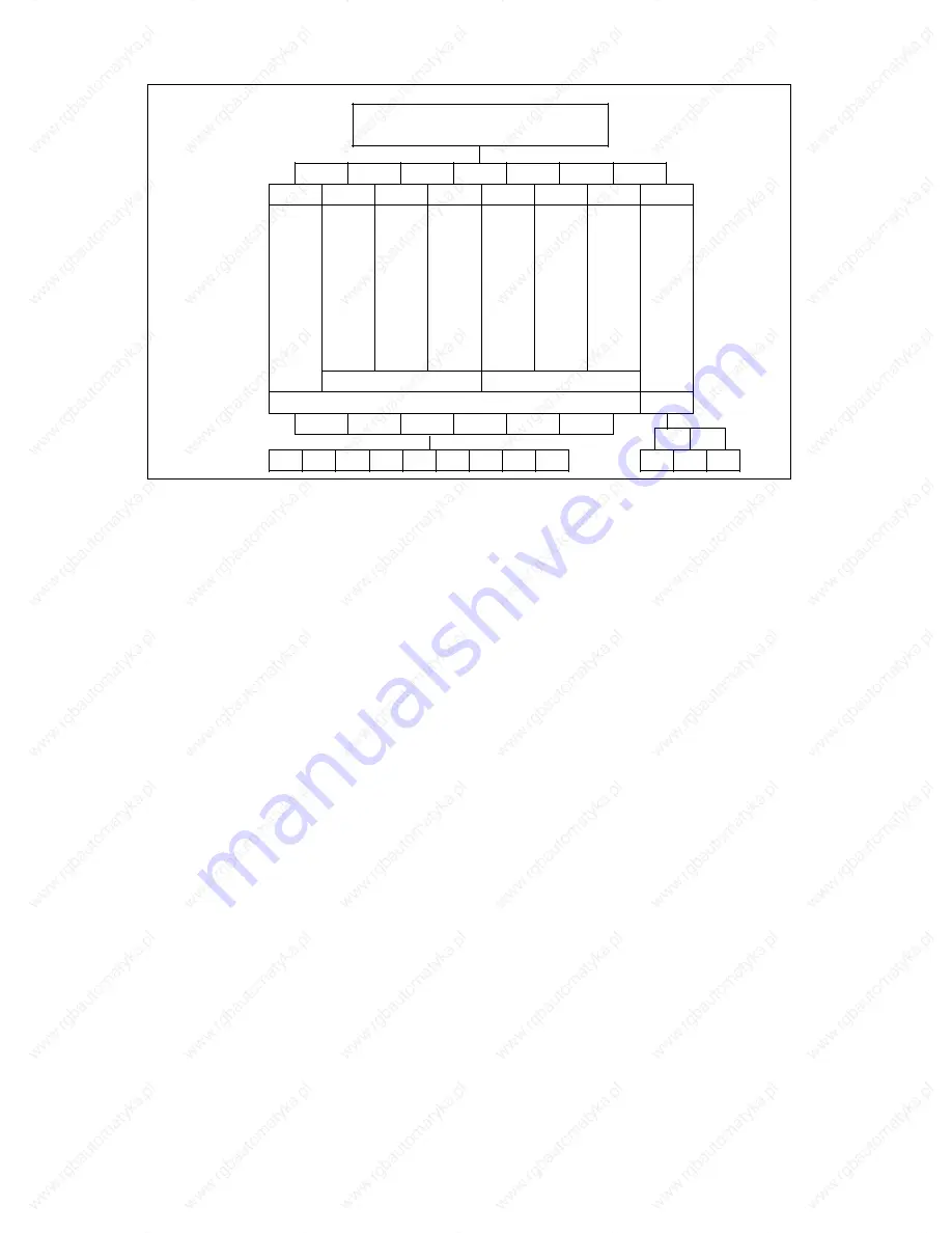
6.1 Introduction to channel structure
Channel structure: programmable allocation of channels
Mode
group
>
Axes/
spindles
Central
part program memory
1
2
3
4
5
6
7
8
X1
Z1
S1
C
S2
Turn-
ing and
milling
T1
Turret
1
X2
Z2
(S1)
T2
Turret
2
Q1
Q2
Q3
Loader
Slide 1
Slide 2
1
2
X1
Z1
S1
C
S2
T1
X2
Z2
T2
X2
Z2
T2
Channel
In addition to the processing channels in which the programs controlling the machine units run,
additional channels can be allocated special tasks. In this case, channels 3 and 6 control the
execution of save programs that can be run by the user after a tool breakage, enabling him to
retract and change the tool as well as restart the program. The spare channel 1 is intended for
a future coordination program able to control the entire procedure. This program will not
necessarily be dedicated to channel 1.
Depending on the workpiece being manufactured, machining programs have to be compiled for
reading in the central part program memory.
6.2
Mode groups
The channels are linked in higher-level mode groups. A single mode group contains the chan-
nels that always have to work simultaneously in the same mode for operational reasons. A
maximum of eight mode groups are permitted.
Within the mode group, each axis can be programmed in each channel. In the above example,
the loader has been allocated its own mode group. This permits operation of the loader
setting-up mode during workpiece production.
The assignment of:
•
NC CPU
NC channels
•
Servo CPU
Measuring circuit addresses
•
NC channels
Mode groups
•
NC axes
Mode groups
•
Spindles
Mode
groups
is effected by way of NC machine data.
©
Siemens AG 1991 All Rights Reserved 6ZB5 410-0HE02
6
–
3
SINUMERIK 880 (PJ)


