background image

Operating instructions

K3G250-RR03-H4

Siemens AG PD LD Nbg.

Translation of the original operating instructions

With regard to cyclic speed loads, note that the rotating parts of
the device are designed for a maximum of one million load
cycles. If you have special questions, consult ebm-papst for
support.

;

Use the device in accordance with its degree of protection.

Information on surface quality

The surfaces of the products conform to the generally applicable industrial
standard. The surface quality may change during the production period.
This has no effect on strength, dimensional stability and dimensional
accuracy.
The color pigments in the paints used perceptibly react to UV light over
the course of time. This does not however in any way affect the
technical properties of the products. The product is to be protected against
UV radiation to prevent the formation of patches and fading. Changes in
color are not a reason for complaint and are not covered by the warranty.

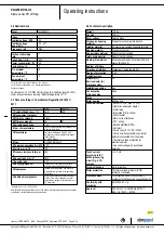
3.5 Mounting data

Strength class of
screws

8.8

;

Secure the screws against unintentional loosening (e.g. use self-
locking screws).

Any further mounting data required can be taken from the product
drawing or Section Chapter 4.1 Mechanical connection.

3.6 Transport and storage conditions

Max. permitted
ambient temp. for
motor (transport/
storage)

+80 °C

Min. permitted
ambient temp. for
motor (transport/
storage)

-40 °C

3.7 Electromagnetic compatibility

EMC immunity to
interference

According to EN 61000-6-2 (industrial
environment)

EMC circuit feedback

According to EN 61000-3-2/3

EMC interference
emission

According to EN 61000-6-3 (household
environment)

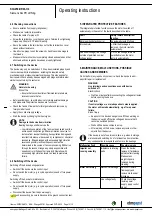
4. CONNECTION AND STARTUP

4.1 Mechanical connection

CAUTION
Risk of cutting and crushing when removing device
from packaging

→ Carefully remove the device from the packaging by grasping

hold of the frame. Never subject to any impact.

→ Wear safety shoes and cut-resistant safety gloves.

CAUTION
Heavy load when unpacking device

Risk of physical injury, such as back injuries.
→ Two people should work together to remove the device from

its packaging.

NOTE
Damage to the device from vibration

Bearing damage, shorter service life
→ The fan must not be subjected to force or excessive vibration

from sections of the installation. #If the fan is connected to air
ducts, the connection should be isolated from vibration, e.g.
using compensators or similar elements. #Ensure stress-free
attachment of the fan to the substructure.

;

The fan may not be handled in the area around the inlet nozzle during
transport and installation.
There is a risk of damage to the impeller.

;

Check the device for transport damage. Damaged devices are not to
be installed.

;

Install the undamaged device in accordance with your application.

CAUTION
Possible damage to the device

If the device slips during installation, serious damage can result.
→ Ensure that the device is securely positioned at its place of

installation until all fastening screws have been tightened.

The fan must not be strained on fastening.

4.2 Electrical connection

DANGER
Voltage on the device

Electric shock
→ Always connect a protective earth first.
→ Check the protective earth.

DANGER
Faulty insulation

Risk of fatal injury from electric shock
→ Use only cables that meet the specified installation

regulations for voltage, current, insulation material, capacity,
etc.

→ Route cables so that they cannot be touched by any

rotating parts.

Item no. 55700-5-9970 · ENU · Change 94781 · Approved 2017-09-12 · Page 6 / 12

ebm-papst Mulfingen GmbH & Co. KG · Bachmühle 2 · D-74673 Mulfingen · Phone +49 (0) 7938 81-0 · Fax +49 (0) 7938 81-110 · [email protected] · www.ebmpapst.com

200

Содержание SIMOTICS M-1PH818

Страница 1: ...www siemens com drives Main motors SIMOTICS M 1PH8 Type 1PH818 1PH822 1PH828 Operating Instructions Installation Instructions Edition 10 2017 ...

Страница 2: ...20 10 2017 15 09 V20 00 ...

Страница 3: ...tructions Edition 10 2017 Introduction 1 Safety information 2 Description 3 Preparations for use 4 Mounting 5 Electrical connection 6 Commissioning 7 Operation 8 Maintenance 9 Spare parts 10 Disposal 11 Service and Support A Technical specifications B Quality documents C Additional documents D ...

Страница 4: ...hose who based on their training and experience are capable of identifying risks and avoiding potential hazards when working with these products systems Proper use of Siemens products Note the following WARNING Siemens products may only be used for the applications described in the catalog and in the relevant technical documentation If products and components from other manufacturers are used thes...

Страница 5: ...the external fan 33 4 6 Interlock circuit for anti condensation heating option 33 4 7 Thermal motor protection 34 4 8 Overheating during periodic duty 34 4 9 Noise emissions 34 4 10 Rotational speed limit values 35 4 11 System inherent frequencies 35 4 12 Torsional loading of the drive train due to faults in the electrical supply 35 4 13 Transport and storage 36 4 13 1 Checking the delivery 36 4 1...

Страница 6: ...59 5 2 9 Roughly aligning the machine 59 5 3 Installing the machine 60 5 3 1 Selecting fixing screws 60 5 3 2 Preconditions for smooth vibration free operation 61 5 3 3 Vibration severity 61 5 3 4 Aligning to the driven machine 62 5 3 5 Mounting the motor 64 5 4 Connecting the cooling water supply 64 5 5 Refitting the external fan 65 6 Electrical connection 67 6 1 Preparation 68 6 1 1 Selecting ca...

Страница 7: ...force ventilated motors 98 8 6 Switching on again after an emergency switching off 98 8 7 Stoppages 98 8 7 1 Avoidance of damage to roller bearings during stoppages 99 8 8 Decommissioning the machine 99 8 9 Re commissioning the machine 100 8 10 Faults 100 8 10 1 Inspections in the event of faults 100 8 10 2 Electrical faults at force ventilated motors 100 8 10 3 Electrical faults at water cooled m...

Страница 8: ... motor 135 10 6 1 Water cooled motor complete 135 10 6 2 Roller bearing cartridge DE with radial shaft sealing ring with regreasing 136 10 6 3 Rolling contact bearing bush drive end belt coupling 137 10 6 4 Rolling contact bearing bush drive end coupling output with regreasing 138 10 6 5 Rolling contact bearing bush drive end coupling output with permanent lubrication 139 10 6 6 Rolling contact be...

Страница 9: ...external fan suction SH225 207 D 5 Operating instructions for the single phase EC external fan pressing SH180 221 D 6 Operating instructions for the single phase EC external fan pressing SH225 235 D 7 Operating instructions for the three phase EC external fan suction SK180 249 D 8 Operating instructions for the three phase EC external fan suction SK225 263 D 9 Operating instructions for the three ...

Страница 10: ... for rolling contact bearing bush drive end with belt coupling with regreasing 137 Table 10 4 Spare parts for rolling contact bearing bush drive end with coupling output with regreasing 138 Table 10 5 Spare parts for rolling contact bearing bush drive end with coupling output with permanent lubrication 139 Table 10 6 Spare parts for rolling contact bearing bush non drive end permanent lubrication ...

Страница 11: ...sible vibration velocity taking into account the vibration displacement and vibration acceleration 62 Figure 5 5 Aligning the motor 63 Figure 6 1 Terminal lug for the grounding conductor for a force ventilated motor 68 Figure 6 2 Terminal lug for the grounding conductor for a water cooled motor 69 Figure 6 3 External fan terminal box schematic representation 77 Figure 6 4 External fan terminal box...

Страница 12: ...10 10 Schematic representation of the motor complete 144 Figure 10 11 Spare parts for external fan type 1PH818 1PH822 145 Figure 10 12 Rolling contact bearing bush drive end with mounted gearing with regreasing 146 Figure 10 13 Rolling contact bearing bush drive end with belt coupling with regreasing 147 Figure 10 14 Rolling contact bearing bush drive end with coupling output with regreasing 148 F...

Страница 13: ...Please contact the Service Center Page 161 if you have any suggestions on how to improve this document Text format features The warning notice system is explained on the rear of the inside front Always follow the safety instructions and notices in these instructions In addition to the safety related warning notices which you must read you will find the text in these instructions is formatted in th...

Страница 14: ...Introduction SIMOTICS M 1PH8 1PH818 1PH822 1PH828 14 Operating Instructions 10 2017 ...

Страница 15: ... setup and safety regulations as well as regulations on the use of personal protective equipment are observed Note Use the services and support provided by the appropriate Service Center Page 161 for planning installation commissioning and servicing work You will find safety instructions in the individual sections of this document Follow the safety instructions for your own safety to protect other...

Страница 16: ...se of caution is necessary when you are near the machine Always pay attention to your safety Also observe the following to prevent accidents General safety regulations applicable in the country where the machine is deployed Manufacturer specific and application specific regulations Special agreements made with the operator Separate safety instructions supplied with the machine Safety symbols and i...

Страница 17: ...ate the machine properly CAUTION Hazardous substances Chemical substances required for the setup operation and maintenance of machines can present a health risk Poisoning skin damage cauterization of the respiratory tract and other health damage may result Read the information in these operating instructions and the product information supplied by the manufacturer Observe the relevant safety regul...

Страница 18: ...mage follow the instructions given below Only touch electronic modules if you absolutely have to work on them The body of the person concerned must have been electrostatically discharged and grounded immediately before any electronic modules are touched Electronic modules should not be brought into contact with electrically insulating materials such as Plastic film Plastic parts Insulating table s...

Страница 19: ...hen operating the converter WARNING Interference voltages when operating the converter When a converter is in operation the emitted interference varies in strength depending on the converter manufacturer type interference suppression measures undertaken On machines with integrated sensors e g PTC thermistors interference voltages caused by the converter may occur on the sensor lead This can cause ...

Страница 20: ... magnetic or electronic data carriers It is forbidden for people with pacemakers to enter the vicinity of the machine Protect the personnel working in the plant by taking appropriate measures such as erecting identifying markings safety barriers and warning signs and giving safety talks Observe the nationally applicable health and safety regulations Do not carry any magnetic or electronic data med...

Страница 21: ...hazardous areas An explosion can occur if the machine is operated in these areas This can result in death serious injury or material damage Never operate this machine in hazardous areas Rating plate The rating plate shows the identification data and the most important technical data The data on the rating plate and the contractual agreements define the limits of proper usage 2 0 1R 1 31 N 81 9 Q1 ...

Страница 22: ...rent IMAX 110 Operating mode 1 335 Weight 115 Code for operating point 1 340 Maximum torque MMAX 120 Rated voltage UN 2 350 Maximum speed nMAX 121 Connection type 2 360 Temperature sensor 130 Rated current IN 2 370 Tachometer resolver 140 Rated power PN 2 380 Cooling method 150 cos φ 2 390 Throughput l min m3 s 160 Rated frequency fN 2 400 System pressure 170 Rated speed nN 2 410 Maximum coolant t...

Страница 23: ...S motor series European low voltage directive The SIMOTICS motor series complies with the requirements of the low voltage directive 2014 35 EU European machinery directive The SIMOTICS motor series does not fall within the area of validity of the machinery directive However the use of the products in a typical machine application has been fully assessed for compliance with the main regulations in ...

Страница 24: ...3358 cert Drive The motor speed is controlled using a converter NOTICE Destruction of the machine when operated directly from the line supply The machine will be destroyed if it is directly connected to the line supply Only operate the machine using a converter Types of construction The motor is supplied with two attached lifting eyes The type construction can be found on the rating plate Vertical...

Страница 25: ...se of the external fan Improper use of the external fan can result in death serious injury and material damage Observe and follow the operating instructions of the external fan See also Additional documents Page 167 External fan Different external fans are used depending on the shaft height and particular motor version Type Version External fan 1PH818 1PH822 Standard version EC external fan with s...

Страница 26: ...cial version of the mounted holding brake The corresponding data in the manufacturers operating instructions do not apply Table 3 3 Technical data of the holding brake Technical data NFF A 63 AH180 NFF A 100 AH225 Braking torque MBrake Nm 1000 1600 Max speed nBrake rpm 3500 3100 Weight incl hollow shaft mbrake kg 63 88 Moment of inertia Jbrake kgm2 0 022 0 051 Total moment of inertia emer gency st...

Страница 27: ...achine s lubricant plate The following standard roller bearing versions are available Table 3 4 Roller bearing versions Design Bearings Standard design and Performance Drive end deep groove ball bearing as spring loaded floating bearing Non drive end deep groove ball bearing as fixed bearing Version for increased radial forces Drive end cylindrical roller bearing as floating bearing Non drive end ...

Страница 28: ...Description SIMOTICS M 1PH8 1PH818 1PH822 1PH828 28 Operating Instructions 10 2017 ...

Страница 29: ...arkings etc to ensure the machine is operated safely within your plant 4 2 Observing the operating mode Observe the machine s operating mode Use a suitable control system to prevent overspeeds thus protecting the machine from damage 4 3 Cooling water quality for water cooled motors The values specified for the cooling water correspond to the requirements for a closed cooling circuit Not all of the...

Страница 30: ...ature If the temperature difference between cooling water and ambient temperature is greater than 5 K this may result in condensation forming in the machine This results in material damage Make sure that the condensation can drain away freely Adopt appropriate measures to achieve the required intake temperature of the cooling water Alternatively dry the ambient air 4 4 Ensuring cooling Note Note a...

Страница 31: ...scharge openings to ensure the required cooling air flow Comply with the conditions of the IP degree of protection More stringent requirements regarding the IP degree of protection may necessitate the installation of suitable filters and special arrangement of the intake and outlet openings Equipment and cables must be connected without strain Figure 4 1 Air guidance from the DE to the NDE schemat...

Страница 32: ...d on the rating plate Machines with pipe connection You must mount and connect pipes and a fan of suitable type and dimensioning to machines that are intended for the connection of pipes and or for operation with an external fan Please observe the following when connecting pipes Additional pressure drop in the system Shipping covers on the ventilation openings must have been removed Preparations f...

Страница 33: ...ional Force ventilated 1PH818 and 1PH822 motors are equipped with electronically commutated motors EC motor NOTICE Voltage fluctuations The electronics of the external fan equipped with EC motor can be damaged as a result of voltage fluctuations Supply the external fan with power from the line supply and not via a frequency converter 4 6 Interlock circuit for anti condensation heating option If th...

Страница 34: ...ed the temperature of the coolant see S2 duty type in DIN EN 60034 1 Use a suitable circuit to ensure that the external fan is appropriately operated NOTICE EC fan control via an input signal The fan motor can overheat if the external EC fan is operated at low fan speeds as a result of the setpoint signal it receives Monitor the motor using the integrated temperature sensors Integrate the temperat...

Страница 35: ...xceeded The vibration limit values according to DIN ISO 10816 3 must not be exceeded 4 12 Torsional loading of the drive train due to faults in the electrical supply In the event of faults in the electrical connection during operation excessive air gap torques can lead to additional mechanical torsional load on the line shaft Note The system planner is responsible for the entire drive train WARNIN...

Страница 36: ... accessed 4 13 2 Lifting and transportation To safely lift and transport the machine the following requirements must be met Personnel operating cranes and fork lift trucks must be appropriately qualified If the motor is packed depending on the weight size and on site conditions lift crates and transport frames using a fork lift truck or a crane with slings Use a crane or fork lift truck suitable f...

Страница 37: ...avity of a load is not located centrally between the attachment points the motor can tip over or slip out of the lifting equipment and fall when it is being transported or lifted This can result in death serious injury or material damage Comply with the handling instructions on the machine when transporting it Be aware of the possibility of different loads on the sling ropes or lifting straps and ...

Страница 38: ...e or spreading equipment NOTICE Damage to the terminal box The terminal box can be damaged when lifting without using suitable spreading equipment Only lift the machine using suitable spreading equipment Pay attention to the lifting capacity of the hoisting gear The weight of the motor is specified on the rating plate Figure 4 4 Lifting the machine schematic representation Preparations for use 4 1...

Страница 39: ... element has been pulled on then you must axially fix the rotor in another way ཱ Sleeve Shaft screw Figure 4 5 Rotor shipping brace Table 4 3 Tightening torque and preloading force for axially fixing the rotor Type Thread in the shaft end Tightening torque Preload 1PH818 M20 50 Nm 12 kN 1PH822 M20 50 Nm 12 kN 1PH828 M24 100 Nm 20 kN WARNING Lifting using the cooling water pipes The cooling water p...

Страница 40: ...ustomer 3 Fit the rotor shipping brace 4 Only use the eyebolts on the bearing shields to transport and lift the motor 4 13 4 Transporting a water cooled motor that has already been in operation If you have already operated the motor and now want to transport it proceed as follows 1 Allow the motor to cool down 2 Remove the connections provided by the customer 3 Drain the cooling water system and p...

Страница 41: ...t in a secure and raised position DANGER Standing under suspended loads If the lifting gear or load handling attachments were to fail the machine could fall This can result in death serious injury or material damage Never remain under or in the immediate vicinity of the machine when it is raised 4 13 6 Storage You can store the machine for up to two years in dry dust free and vibration free rooms ...

Страница 42: ...otect the motor from shocks and humidity Cover the motor properly Avoid contact corrosion Every three months remove the shipping brace Rotate the shaft extension by hand Then reattach the rotor shipping brace Protection against humidity If a dry storage area is not available then take the following precautions Wrap the machine in a material that absorbs moisture Then pack the machine in an airtigh...

Страница 43: ...ng can be damaged during transport In this case make sure that the customer uses a rotor shipping brace Long term storage If you are storing a machine for more than six months you must check its condition every six months Check the machine for damage Carry out any necessary maintenance work Document all preservation measures taken so that they can be reversed before the machines are put back into ...

Страница 44: ...ce is reduced This can result in voltage flashovers which can destroy the winding Condensation can cause rusting inside the machine Make sure that the condensation can always drain away freely 4 13 8 Protect the cooling water system of water cooled motors When the units are delivered the high grade steel cooling water pipe system is not filled with cooling water When you put the motor into storage...

Страница 45: ...back into service 4 14 Converter operation 4 14 1 Connecting to a converter Selecting and connecting the cable Use Motion Connect cables or symmetrically constructed shielded cables to connect the motor to a converter The cable shielding made up of as many strands as possible must have good electrical conductivity Braided shields made of copper or aluminum are well suited The shield is connected a...

Страница 46: ...hine as well as between the motor and the converter Limit the voltage rate of rise by using an output filter to dampen harmonic components in the output voltage 4 14 2 Insulated bearings for converter operation If the machine is operated with a low voltage converter such as SINAMICS G150 S150 S120 then an insulated bearing and a speed encoder with insulated bearings option is mounted at the non dr...

Страница 47: ...tallation work e g installing an automatic lubrication system or a non insulated vibration sensor ensure the bearing insulation is not bridged Contact your Service Center if necessary See also Service and Support Page 161 Preparations for use 4 14 Converter operation SIMOTICS M 1PH8 1PH818 1PH822 1PH828 Operating Instructions 10 2017 47 ...

Страница 48: ...Preparations for use 4 14 Converter operation SIMOTICS M 1PH8 1PH818 1PH822 1PH828 48 Operating Instructions 10 2017 ...

Страница 49: ...ked and ready for mounting at the installation location Note Measure the insulation resistance of the winding before starting installation work Wherever possible measure the insulation resistance of the winding before starting installation work If the insulation resistance lies below the specified value take appropriate remedial measures These remedial measures may necessitate the machine being re...

Страница 50: ...sting the insulation resistance and polarization index Page 50 5 1 3 Testing the insulation resistance and polarization index WARNING Hazardous voltage at the terminals During and immediately after measuring the insulation resistance or the polarization index PI of the stator winding hazardous voltages may be present at some of the terminals Contact with these can result in death serious injury or...

Страница 51: ...0 Urated rated voltage see the rating plate Umeas DC measuring voltage RC minimum insulation resistance at reference temperature of 40 C Conversion to the reference temperature When measuring with winding temperatures other than 40 C convert the measuring value to the reference temperature of 40 C according to the following equations from IEEE 43 2000 1 RC KT RT RC Insulation resistance converted ...

Страница 52: ...table Measuring the polarization index 1 To determine the polarization index measure the insulation resistances after one minute and ten minutes 2 Express the measured values as a ratio PI Rinsul 10 min Rinsul 1 min Many measuring devices display these values automatically following the measurement For insulation resistances 5000 MΩ the measurement of the PI is no longer meaningful and consequentl...

Страница 53: ...e of the services offered by the local Service Center Page 161 5 2 2 Checking the load handling attachments Inspect the load handling attachments such as the load stands lifting eyes and ring bolts and also the lifting gear before lifting the machine Inspect the load handling attachments on the machine for possible damage Replace any load handling attachments that are found to be damaged Check bef...

Страница 54: ...on protection could result in damage to the surfaces of the machine parts 2 Then lightly oil the bare surfaces again 5 2 4 Mounting the output elements Balance quality The rotor is dynamically balanced For shaft extensions with featherkeys the balancing type is specified using the following coding on the face of the drive end of the shaft H Balancing with half a feather key F Balancing with a full...

Страница 55: ...maintain the balancing quality you have the following options If the output element is shorter than the feather key for balancing type H Machine off the section of feather key protruding from the shaft contour and output element in order to maintain the balance quality If the output element is mounted up to the shaft shoulder for motors with full key balancing F or if the output element is longer ...

Страница 56: ...e machine refer to the information on the lifting plate Comply with the specified spreading angles Do not exceed the maximum lifting acceleration and lifting speed specified on the lifting plate Lift the machine without jerking it Acceleration a 0 4 g 4 m s2 Velocity v 20 m min Use only the load carrying device on the stator frame for lifting WARNING Transport for a different type of construction ...

Страница 57: ...sition In order to obtain easy and safe access to the underside of the machine place it in a secure and raised position DANGER Standing under suspended loads If the lifting gear or load handling attachments were to fail the machine could fall This can result in death serious injury or material damage Never remain under or in the immediate vicinity of the machine when it is raised NOTICE Damage due...

Страница 58: ...Siemens Service Center Page 161 5 2 7 Open condensation drain holes air cooled motor L12 If the machine is ordered with option L12 then for types 1PH818 and 1PH822 a water drain hole with plugs is provided in the DE and NDE bearing shields For type 1PH828 there are water drain holes without plugs at the DE and NDE Figure 5 3 Water drain holes for types 1PH818 1PH822 Mounting 5 2 Lift the machine t...

Страница 59: ...ti corrosion protection paint has been removed from the mating faces such as the machine mounting feet flange There is no condensation present within the machine Setting down the machine Set down the machine slowly and carefully at the installation location to avoid any impact 5 2 9 Roughly aligning the machine Requirement The transmission element such as a coupling half has already been pulled on...

Страница 60: ...ully align the machine to the driven machine NOTICE Improper handling Mounting parts such as temperature sensors or speed sensors are attached to the machine and could be ripped off or destroyed as a result of improper handling This could lead to machine malfunctions extending even to total loss of the machine Where necessary use suitable steps when performing installation work on the machine Do n...

Страница 61: ...y with the output element Please take care to ensure that the vibration severity specified in accordance with ISO 10816 is not exceeded at the defined measuring points on the motor By doing this you can ensure problem free operation and a long service life Maximum permitted vibration severity The values for the maximum permitted radial and axial vibration severity must both be maintained Table 5 2...

Страница 62: ...and horizontal alignment The following measures are required in order to compensate any radial offset at the coupling and to horizontally adjust the motor with respect to the driven machine The contact surfaces of the motor feet must lie on one plane Place shims under the motor feet to position it vertically and to prevent any stress distortion The number of shims should be kept as low as possible...

Страница 63: ...th no offset This ensures that no additional forces affect their bearings during operation 2 Perform the fine adjustments with plates under the entire motor foot Figure 5 5 Aligning the motor Table 5 4 Permissible deviations when aligning the motor Permissible deviations Radial shaft offset x Axial shaft offset y Flexible coupling 0 05 mm 0 05 mm Mounting 5 3 Installing the machine SIMOTICS M 1PH8...

Страница 64: ...the motor is to be only flange mounted then the maximum speed nmax is reduced for rigid foundations according to the following table Type Maximum speed nmax 1PH818 3000 1 min 1PH822 2500 1 min 1PH828 2000 1 min Maximum speed for a rigid foundation and flange mounting 5 4 Connecting the cooling water supply The inlet and outlet sockets for the cooling water supply are situated on the non drive end ...

Страница 65: ... the water pipes 6 Ensure that the maximum permissible operating pressure does not exceed 6 bar The pressure drop is determined by the machine type and the shaft height Table 5 5 Rate of flow and pressure drop Type Flow rate Pressure drop 1PH8 184 15 l min 0 6 bar 1PH8 186 15 l min 0 7 bar 1PH8 224 20 l min 0 6 bar 1PH8 226 20 l min 0 6 bar 1PH8 228 20 l min 0 6 bar 1PH8 284 35 l min 0 6 bar 1PH8 ...

Страница 66: ...Mounting 5 5 Refitting the external fan SIMOTICS M 1PH8 1PH818 1PH822 1PH828 66 Operating Instructions 10 2017 ...

Страница 67: ...ult in material damage to the machine or even in total failure which could in turn lead indirectly to material damage to the system Tighten the screwed connections to the specified tightening torques Observe any specifications regarding the materials from which fixing elements must be made When performing servicing check the fastenings See also Tightening torques for screw and bolt connections Pag...

Страница 68: ... accordance with IEC EN 60204 1 Connect the ground conductor to the end shield of the motor There is a fixing lug for the ground conductor at the designated connection point The fixing lug is suitable for grounding high frequency currents using HF ribbon cable with appropriately formed conductor ends When making connections ensure the following the connecting surface is bare and protected against ...

Страница 69: ...2 Terminal designation According to IEC EN 60034 8 the following basic definitions apply to the terminal designations for 3 phase machines Table 6 1 Terminal designations using the 1U1 1 as an example 1 U 1 1 Designation x Index for pole assignment for pole changing machines where applicable A lower index signifies a lower speed Special case for split winding x Phase designation U V W x Index for ...

Страница 70: ...prevents contact corrosion Arrange the exposed connecting cables in the terminal box so that the PE conductor has excess length and the insulation of the cable strands cannot be damaged Close off unused bushings with a metal threaded plug This is the way to achieve a high frequency proof shielding 6 2 4 Electrical connection data Cable entry and technical connection data depend on the mounted term...

Страница 71: ...on IEC EN 60204 1 or IEC EN 60364 5 32 6 2 5 Connection with cable lugs 1 To connect the cables to the main terminals select cable lugs that match the necessary cable cross section and appropriate screw size The connectable cable cross section is determined by the cable lug size for example Cable lug in accordance with DIN 46234 from 35 mm2 to 185 mm2 Cable lug in accordance with DIN 46235 from 35...

Страница 72: ...ws depends on the size of the screw see Case A in the table in Chapter Tightening torques for screw and bolt connections Page 163 Connection using a cable lug at terminal boxes 1XB7 322 1XB7 422 Customer connecting cable Internal motor connecting cable Copper spacer ring Connection using a cable lug at terminal boxes 1XB7 700 1XB7 712 Customer connecting cable Connection bar Electrical connection ...

Страница 73: ...rounding components could burn This could result in material damage to the machine or even in total failure which could in turn lead to indirect material damage to the system Retighten the clamping nuts after approximately 24 hours and then again after approximately four weeks Make sure that the terminals are de energized before you tighten the nuts 6 2 7 Stepless mating face for the seal in the t...

Страница 74: ...ee of protection cable routing type permissible cable diameter etc 2 Then close the terminal box with the terminal box cover fixing screws See also Tightening torques for screw and bolt connections Page 163 6 2 9 Internal equipotential bonding The internal equipotential bonding between the grounding terminal in the box enclosure and the motor frame is established through the terminal box retaining...

Страница 75: ...plate matches the connection data Cable glands are not included in the scope of supply Close unused cable entries otherwise the degree of protection is not maintained The line voltage corresponds to the quality attributes laid down in DIN EN 50160 and the defined standard voltages laid down in DIN IEC 60038 Procedure 1 Open the terminal box of the external fan and route the cables into it The cabl...

Страница 76: ... fan is not in operation After a power failure or when the power has been disconnected the external fan starts up automatically again when the voltage is restored The external fan can automatically switch on and switch off as a result of its inherent function See also Interlock circuit for the external fan Page 33 NOTICE Overheating when the factory installed jumper is removed If the company opera...

Страница 77: ...ternal fan suction SK180 Page 249 6 3 2 1 Connecting an EC external fan The external fan is connected in the external fan terminal box If necessary you can rotate the external fan through 90 Figure 6 3 External fan terminal box schematic representation NOTICE Short circuit due to standing water Water that accumulates at the cable glands can result in a short circuit It is not permissible that the ...

Страница 78: ...ction of rotation arrow Operation with the wrong direction of rotation can cause overheating or destruction of the motor Ensure that the external fan is operated in the proper direction of rotation The direction of rotation arrow and the direction of movement of the fan impeller are indicated on the rear side of the blower If necessary change the direction of rotation by interchanging two phase co...

Страница 79: ...E NDE DE 2 25 2 25 1 98 76 2 0 17 1PH822 0 1 Z 1PH822 1 1 Z DE NDE NDE DE 2 25 2 25 1 98 76 2 0 31 1PH8 open circuit ventilated degree of protection IP23 option L75 1PH818 3 1 Z 1PH818 4 1 Z DE NDE NDE DE 2 25 2 25 1 98 76 3 0 21 1PH822 3 1 Z 1PH822 4 1 Z DE NDE NDE DE 2 25 2 25 1 98 76 3 0 33 1 60 Hz operation only permissible with throttle plate 2 Speed ranges 1PH818 up to 5000 rpm 1PH822 up to ...

Страница 80: ...on of rotation of the fan impeller can be seen at the rear of the fan 6 3 2 4 Attached air discharge throttle plate option L75 When operated from a 60 Hz line supply you require the air discharge throttle plate provided in the terminal box NOTICE Operation without air discharge throttle plate The external fan motor can be damaged if it is operated on a 60 Hz line supply without air discharge throt...

Страница 81: ...etal plate Figure 6 5 Throttle plate for suction type ventilation DE to NDE Fixing screws for air discharge throttle metal plate Air discharge throttle metal plate Figure 6 6 Throttle plate for forced draft ventilation NDE to DE Electrical connection 6 3 Auxiliary circuits SIMOTICS M 1PH8 1PH818 1PH822 1PH828 Operating Instructions 10 2017 81 ...

Страница 82: ...s reduce the mounting installation time and costs and increase operational reliability Push the connector of the DRIVE CLiQ cable into the socket until the catch spring latches into place Pay attention to the coding of the connector Cable outlet directions The sensor module is mounted on the motor terminal box The sensor module can be rotated through approximately 235 You can change the cable outl...

Страница 83: ...brake can be found in the operating instructions supplied by the manufacturer in the Page 169 appendix 6 3 5 Connecting the temperature sensor The temperature sensor is connected to the signal connector together with the speed encoder signal For the version without speed encoder the temperature sensor is connected at the terminal strip The motor has a reserve temperature sensor which is also conne...

Страница 84: ... suited The shield is connected at both ends at the motor and converter Keep unshielded cable ends as short as possible In order to ensure that high frequency currents are efficiently discharged provide a 360 contact through a large surface area at the converter and at the motor Use for instance EMC glands at the cable entries Measures to reduce bearing currents To specifically reduce and prevent ...

Страница 85: ...r current can arise if there is a ground fault on the output side Neither the PE conductors of normally rated multi core connecting cables nor the PE connecting points of normal terminal boxes are suitable for this purpose Material damage can result Use an appropriately sized PE conductor Connect the PE conductor to the grounding terminal on the motor enclosure Electrical connection 6 3 Auxiliary ...

Страница 86: ...Electrical connection 6 3 Auxiliary circuits SIMOTICS M 1PH8 1PH818 1PH822 1PH828 86 Operating Instructions 10 2017 ...

Страница 87: ...netic fields at the workplace Clearly mark the boundaries of the areas where standing is permitted People who need to use electronic or magnetic medical aids such as pacemakers hearing aids implants or similar devices are at particularly high risk Such persons must undergo an occupational health assessment Observe the following measures Personal protective measures Ensure that you never wear or ca...

Страница 88: ...e following information is provided regarding the state of the winding insulation Is the winding head insulation conductively contaminated Has the winding insulation absorbed moisture As such you can determine whether the machine needs commissioning or any necessary measures such as cleaning and or drying the winding Can the machine be put into operation Must the windings be cleaned or dried Detai...

Страница 89: ...o prevent it from being thrown out and cut back to roughly half its length if the rotor has balancing type H standard type The unused shaft extension is covered and protected against accidental contact The rotor can spin without coming into contact with the stator The bearing insulation is not bridged Electrical connection The grounding and equipotential bonding connections have been made correctl...

Страница 90: ...ored for more than two years in a dry dust free and vibration free room prepare for commissioning as follows Replace the rolling contact bearings on motors with lifetime lubrication Replace the grease in motors with re greasing system If stored under less favorable conditions the bearings or the grease must be replaced after a storage period of approx 18 months Table 7 1 Minimum radial forces Type...

Страница 91: ...ensure that the parameters of the frequency converter have been assigned correctly Use appropriate commissioning tools such as Drive ES or STARTER NOTICE Operation noise or abnormal noises The motor can be damaged by improper handling during transport storage or set up If a damaged motor is operated damage to the winding bearings or complete destruction of the motor can be the result If the motor ...

Страница 92: ...temperatures until they have reached steady state values Check the machine for noise or vibrations on the bearings or bearing shields as it runs 5 In case of uneven running or abnormal noise switch off the machine As the machine runs down identify the cause If the mechanical operation improves immediately after the machine is switched off then the cause is magnetic or electrical If the mechanical ...

Страница 93: ...emperature Alarm 115 C Shutting down 120 C Normal operation Measure the normal operating temperature of the bearings Top at the installation location in C Set the values for shutdown and warning corresponding to the operating temperature Top Table 7 3 Set values for monitoring the bearing temperatures Set value Temperature Alarm Toperation 5 K 115 C Shutting down Toperation 10 K 120 C Commissionin...

Страница 94: ...Commissioning 7 6 Set values for monitoring the bearing temperature optional SIMOTICS M 1PH8 1PH818 1PH822 1PH828 94 Operating Instructions 10 2017 ...

Страница 95: ... and live parts Rotating or live parts are dangerous If you remove the required covers this can result in death serious injury or material damage Any covers that prevent live electrical or rotating parts from being touched ensure compliance with a particular degree of protection or are required for ensuring proper air flows and hence effective cooling must not be opened during operation WARNING Fi...

Страница 96: ...ensation can drain away freely NOTICE Non periodic duty In all of the operating modes always operate the external fan according to DIN EN 60034 1 For non periodic operation it is possible that the machine is thermally overloaded This can result in damage to the machine In the case of extended non operational periods the fan should be in operation until the machine has approximately reached the tem...

Страница 97: ...can burst This can result in death serious injury or material damage Do not connect the cooling water supply until the motor has cooled down 8 3 Switching on the machine After starting the motor observe it for a while to see if it is running smoothly and check the monitoring devices Monitor operation and the monitoring devices regularly and record the values you read off NOTICE Speed monitoring Th...

Страница 98: ...f the external fan during longer standstill periods Leave the fan on for approximately 30 minutes after switching off the motor to avoid overheating of the motor Follow the operating instructions of the converter 8 6 Switching on again after an emergency switching off Check the machine before recommissioning the driven machine after an Emergency Off Eliminate all the causes that have led to the em...

Страница 99: ...amage such as brinelling or corrosion for example During stoppages regularly start the machine up for a brief period once a month As a minimum rotate the rotor several times If you have uncoupled the machine from the driven machine and secured the rotor with a rotor shipping brace then remove this before turning the rotor over or starting the machine up Make sure that the resting position of the r...

Страница 100: ...ons in the event of faults Natural disasters or unusual operating conditions such as overloading or short circuit are faults that overload the machine electrically or mechanically Immediately perform an inspection after such faults Correct the cause of the fault as described in the respective remedial measures section Repair any damage to the machine 8 10 2 Electrical faults at force ventilated mo...

Страница 101: ...r form the automatic motor identification X External fan is not running Check the external fan and its connections X Wrong direction of rotation of the external fan Check the electrical connections to the external fan X Reduced air intake Check the air ducts clean the machine 8 10 3 Electrical faults at water cooled motors Note When operating the machine with a converter also refer to the operatin...

Страница 102: ... correct intake temperature 8 10 4 Mechanical faults The following table shows the possible causes of and remedial measures for mechanical faults Table 8 3 Mechanical faults Grinding noise Overheating Radial vibrations Axial vibrations Possible causes of faults Remedial measures X Rotating parts are grinding Establish the cause and realign the parts X Rotor not balanced Decouple the rotor and then...

Страница 103: ...re grease X X Insufficient lubrication Grease the bearings as instructed X X Bearing canted Properly install the bearing X X Insufficient bearing play Contact the Service Center X Excessive bearing play Contact the Service Center X X Bearing corroded Replace the bearing Check the seals X Too much grease in bearing Remove surplus grease X Wrong grease in the bearing Use the correct grease X Frictio...

Страница 104: ...Operation 8 10 Faults SIMOTICS M 1PH8 1PH818 1PH822 1PH828 104 Operating Instructions 10 2017 ...

Страница 105: ...egulations at the place of installation When using the machine within the European Union comply with the specifications laid down in EN 50110 1 regarding safe operation of electrical equipment Note Service Center Please contact the Service Center Page 161 if you require support with servicing maintenance or repair 9 1 Observe the operating instructions of the components When carrying out any maint...

Страница 106: ...immediate death serious injury or material damage Perform regular maintenance on the machine CAUTION Dust disturbances when working with compressed air When cleaning with compressed air dust metal chips or cleaning agents can be whirled up Injuries can result When cleaning using compressed air make sure you use suitable extraction equipment and wear protective equipment safety goggles protective s...

Страница 107: ...ance measures can be specified here 9 2 1 Inspections in the event of faults Natural disasters or unusual operating conditions such as overloading or short circuit are faults that overload the machine electrically or mechanically Immediately perform an inspection after such faults 9 2 2 Initial inspection Perform the following checks after approximately 500 operating hours or at the latest after s...

Страница 108: ...ng bolts screws for the mechanical and electrical connections have been securely tightened X The winding insulation resistances are sufficiently high X Any bearing insulation has been fitted as shown on plates and labeling X Cables and insulating parts and components are in good condition and there is no evidence of discoloring X Condensation can freely flow away X You can perform these checks whi...

Страница 109: ...ation resistance during the course of maintenance work Measuring the insulation resistance and polarization index PI provides information on the condition of the machine It is therefore important to check the insulation resistance and the polarization index at the following times Before starting up a machine for the first time After an extended period in storage or downtime Within the scope of mai...

Страница 110: ...d with a regreasing device Depending on the type of load a deep groove ball bearing or a cylindrical roller bearing is fitted as a floating bearing on the drive end The DE bearing contains built in compression springs that help to rebalance the axial play of the external bearing rings See also Checks to be carried out prior to commissioning Page 89 9 2 6 4 Lubrication The specified grease data app...

Страница 111: ...alternatively for horizontal type of construction with reduced lubrication interval Worked penetration DIN ISO 2137 220 295 0 1 mm Operating temperature range At least 20 C 140 C C Dropping point DIN ISO 2176 At least 200 C C Basic oil viscosity DIN 51562 1 Approx 100 mm s at 40 C Approx 10 mm s at 100 C mm s Additive Antioxidation AO Anti Wear AW No solid lubricants Alternatively Extreme Pressure...

Страница 112: ...or standard applications the following high quality greases are recommended for roller bearings for vertical and horizontal motor types of construction due to their technical attributes Table 9 5 Roller bearing greases for vertical and horizontal types of construction Manufacturer Grease type ExxonMobil Unirex N3 Esso Fuchs Renolit H443 HD88 Lubcon Turmoplex 3 FAG Arcanol Multi 3 For motors with a...

Страница 113: ...he actual number of operating hours NOTICE Relubrication intervals The relubrication intervals for roller bearings are different from the servicing intervals for the machine The roller bearings may be damaged if the relubrication intervals are not complied with Pay attention to the instructions on the lubricant plate Grease replacement intervals The grease replacement intervals in these operating ...

Страница 114: ...nents This can result in death serious injury or material damage 1 Clean the grease nipple before regreasing Gradually press in an appropriate type and amount of grease as stamped on the lubricant plate and specified in these operating instructions The roller bearing temperature initially increases noticeably After the excess grease has been displaced out of the bearing the temperature will return...

Страница 115: ...nstruction plate The shaft rotates so that the new grease is evenly distributed throughout the bearing The bearing temperature initially increases noticeably After the excess grease has been displaced out of the bearing the temperature will return to the normal value Figure 9 1 Flat grease nipples and schematic representation for types 1PH818 and 1PH822 Maintenance 9 2 Inspection and maintenance S...

Страница 116: ...over To remove the spent grease proceed as follows 1 Remove the transmission element 2 Remove the spent grease At the DE unscrew the outer bearing cover and empty the spent grease from the outer bearing cover At the NDE remove the cover of the speed sensor and the cover of the spent grease chamber Empty the spent grease chamber Note For types 1PH818 and 1PH822 you must remove the fan before removi...

Страница 117: ...injury or material damage can result For safety reasons it is not permissible to make any unauthorized modifications or changes to the fan The external fan can automatically switch on and switch off as a result of its inherent function After a power failure or when the power has been disconnected the external fan starts up automatically again when the voltage is restored Wait until the external fa...

Страница 118: ...is no longer guaranteed There is a risk of injury Only change the filter when the fan is stationary 1 Unscrew the fan guard and remove the old filter mat 2 Insert the new filter mats and screw the fan guard back into position You can order the filter mat as a spare part Spare parts external fan Page 145 Spare parts kits Page 133 Ordering spare parts via the Internet Page 134 9 2 6 8 Maintaining te...

Страница 119: ...lish this information when dismantling them and make a note of it for the purpose of reassembly Document the type dimensions and arrangement of the parts so that you will be able to reassemble the machine to its original state Use suitable tools to disassemble the machine Take measures to prevent parts from dropping down before you dismantle them e g by replacing fastening elements with extra long...

Страница 120: ...in any detailed information about the type and dimensions of fixing elements etc NOTICE Removing centered parts Centered parts can be damaged if removed improperly with unsuitable tools Use pullers or suitable devices to remove parts and components attached to the motor shaft Disassembly 1 Unscrew the water pipes 2 Ensure you do not damage insulation when dismantling the device Check the insulatio...

Страница 121: ... removed improperly with unsuitable tools Use pullers or suitable devices to remove parts and components attached to the motor shaft Disassembly 1 Ensure you do not damage insulation when dismantling the device Check the insulation for possible damage prior to re installing 2 To disassemble the motor disconnect the connecting cables from the terminals and the entry plate from the terminal box hous...

Страница 122: ...nd Support Page 161 If roller contact bearings with an insulated design are installed use roller bearings of the same type as spare parts This will prevent any bearing damage being caused by bearing currents 9 3 5 Removing and installing the protecting ring The protecting ring acts as an outer bearing seal It sits on the shaft outside the bearing end shield Disassembly Once the coupling is detache...

Страница 123: ...hat the windings are not damaged For water cooled motors also ensure that the cooling water pipes are not damaged For assembly proceed in reverse order WARNING Lifting using the cooling water pipes The cooling water pipe system has not been designed so that it can be used to lift the motor The machine can fall when lifted Death serious injury or material damage will result Only use the eyebolts on...

Страница 124: ...ling gap on the active part of the bearing must also be resealed with a suitable silicone free sealant during assembly Check the sealing elements fitted e g at the terminal boxes and replace them if they do not provide an adequate seal Follow the manufacturer s application and safety instructions when using the sealant Replace parts that are subject to wear such as the adjusting springs Installing...

Страница 125: ...ng elements for example on the terminal box for elasticity aging or damage Replace any sealing elements if they are no longer fully effective ແ ໂ ໃ ໄ End shields Housing Sealing gap Protective tube Figure 9 4 Sealing gap between the enclosure and bearing shields schematic representation Installing the active parts of the bearings When installing replacing the bearing ensure that an insulated beari...

Страница 126: ... motor Page 123 9 3 9 Relocating the external fan type 1PH828 Subsequently moving the external fan from NDE to DE or vice versa must only be carried out by qualified personnel or a Siemens Service Center Page 161 9 3 10 Removing and mounting the external fan WARNING Live parts Contact with live parts can cause death serious injury or material damage 1 Before carrying out any maintenance work on th...

Страница 127: ... and remove the external fan 3 For mounting proceed in reverse order Figure 9 6 Unscrewing the external fan 1PH818 1PH822 Figure 9 7 Unscrewing the external fan 1PH828 See also Operating instructions for the three phase EC external fan suction SK180 Page 249 Maintenance 9 3 Repair SIMOTICS M 1PH8 1PH818 1PH822 1PH828 Operating Instructions 10 2017 127 ...

Страница 128: ...s Page 18 Preparation For 1PH818 and 1PH822 motors the speed encoder can only be removed and replaced if the external fan Page 126 has been removed ແ ໂ ໃ ໄ Shaft Speed encoder Torque arm Encoder cover Figure 9 8 Detailed view of the speed encoder 1 Unscrew the cover of the speed encoder 2 Detach the electrical connection Pull the cable carefully out of its holder Pull out the connector 3 Remove th...

Страница 129: ...l screw This will then drop out 3 Remove the speed encoder Mounting the speed encoder 1 Screw the torque arm to the speed encoder tightening the two screws by hand 2 Use the M5x50 screw to secure the speed encoder over the internal cone ensuring a tightening torque of 5 Nm at the shaft extension 3 Attach the torque arm to the bearing cover with a tightening torque of 3 Nm 4 Loosen the screws of th...

Страница 130: ...r cover Take care that you do not catch the cable as you screw it in ཱ ི Figure 9 9 Electrical connection of the speed sensor 9 3 13 Replacing the DRIVE CLiQ interface encoder module Only trained Siemens service engineers Page 161 are authorized to replace the DRIVE CLiQ interface sensor module NOTICE Electrostatic discharge Electronic modules contain components that can be destroyed by electrosta...

Страница 131: ...the sensor module on other motors Do not replace the sensor module with a sensor module from a different motor 9 3 14 Touch up any damaged paintwork If the paint is damaged it must be repaired in order to protect the unit against corrosion Note Paint system Contact the Service Center Page 161 before you repair any paint damage They will provide you with more information about the correct paint sys...

Страница 132: ...Maintenance 9 3 Repair SIMOTICS M 1PH8 1PH818 1PH822 1PH828 132 Operating Instructions 10 2017 ...

Страница 133: ...e type and serial number from the bar code on the rating plate Note The graphics in this chapter are schematic representations of the basic versions They are used for spare parts definitions The supplied version may differ in details from these representations 10 2 Spare parts kits The spare parts are bundled with the necessary wearing parts in a logical way so as to create spare parts kits The fo...

Страница 134: ...ring spare parts via the Internet You can use Spares on Web to determine the order numbers for motor spare parts quickly and easily Spares on Web https www automation siemens com sow A short description of how to use Spares on Web is available on the Internet Guide for Spares on Web http support automation siemens com WW news en 25248626 10 5 Anti condensation heating The anti condensation heater ...

Страница 135: ... Rotor complete 4 00 Spare parts kit drive end bearing 10 00 Stator housing with laminated core winding and cooling water pipe system 55 00 Spare parts kit speed encoder 10 35 Hoisting lug 5 00 Bearing shield drive end 20 00 Terminal box 6 00 Bearing shield non drive end 99 00 Special built on parts On request Spare parts 10 6 Water cooled motor SIMOTICS M 1PH8 1PH818 1PH822 1PH828 Operating Instr...

Страница 136: ...ve end with mounted gearing with regreasing Number Designation Number Designation 3 00 Spare parts kit drive end bearing Deep groove ball bearing floating bearing Radial shaft sealing ring Inner ring 3 60 Inner bearing cover 3 20 Outer bearing cover 3 80 Grease nipple 3 45 Corrugated spring compression springs On request Spare parts 10 6 Water cooled motor SIMOTICS M 1PH8 1PH818 1PH822 1PH828 136 ...

Страница 137: ...bearing bush drive end with belt coupling with regreasing Number Designation Number Designation 3 00 Spare parts kit drive end bearing Cylindrical roller bearing floating bearing Protecting ring rotating 3 60 Inner bearing cover 3 20 Outer bearing cover 3 80 Grease nipple On request Spare parts 10 6 Water cooled motor SIMOTICS M 1PH8 1PH818 1PH822 1PH828 Operating Instructions 10 2017 137 ...

Страница 138: ...aring bush drive end with coupling output with regreasing Number Designation Number Designation 3 00 Spare parts kit drive end bearing Deep groove ball bearing floating bearing Protecting ring rotating 3 60 Inner bearing cover 3 20 Outer bearing cover 3 80 Grease nipple 3 45 Corrugated spring On request Spare parts 10 6 Water cooled motor SIMOTICS M 1PH8 1PH818 1PH822 1PH828 138 Operating Instruct...

Страница 139: ... 10 5 Spare parts for rolling contact bearing bush drive end with coupling output with permanent lubrication Number Designation 3 00 Spare parts kit drive end bearing Deep groove ball bearing floating bearing Protecting ring rotating 3 45 Corrugated spring compression springs On request Spare parts 10 6 Water cooled motor SIMOTICS M 1PH8 1PH818 1PH822 1PH828 Operating Instructions 10 2017 139 ...

Страница 140: ... Table 10 6 Spare parts for rolling contact bearing bush non drive end permanent lubrication Number Designation 4 00 Spare parts kit non drive end bearing Deep groove ball bearing locating bearing Retaining ring 4 60 Inner bearing cover On request Spare parts 10 6 Water cooled motor SIMOTICS M 1PH8 1PH818 1PH822 1PH828 140 Operating Instructions 10 2017 ...

Страница 141: ...aring cartridge NDE with regreasing type 1PH818 1PH822 Number Designation Number Designation 4 00 Spare parts kit NDE bearing Deep groove ball bearing locating bearing Retaining ring 4 80 Grease nipple 4 60 Inner bearing cover 4 90 Cover of spent grease chamber On request Spare parts 10 6 Water cooled motor SIMOTICS M 1PH8 1PH818 1PH822 1PH828 Operating Instructions 10 2017 141 ...

Страница 142: ...part roller bearing cartridge NDE with regreasing type 1PH828 Number Designation Number Designation 4 00 Spare parts kit NDE bearing Deep groove ball bearing locating bearing Retaining ring 4 80 Grease nipple 4 60 Inner bearing cover On request Spare parts 10 6 Water cooled motor SIMOTICS M 1PH8 1PH818 1PH822 1PH828 142 Operating Instructions 10 2017 ...

Страница 143: ... bearing bush non drive end with regreasing Number Designation Number Designation 4 00 Spare parts kit non drive end bear ing Deep groove ball bearing locating bearing Shrink ring 4 80 Grease nipple 4 60 Inner bearing cover 4 90 Cover of spent grease chamber On request Spare parts 10 6 Water cooled motor SIMOTICS M 1PH8 1PH818 1PH822 1PH828 Operating Instructions 10 2017 143 ...

Страница 144: ... 00 Spare parts kit NDE bearing 10 00 Stator housing with laminated core and winding 4 00 Spare parts kit DE bearing 10 35 Eyebolt 5 00 Bearing shield DE 20 00 Terminal box 6 00 Bearing shield NDE 32 00 External fan 8 00 Rotor complete 55 10 Spare parts kit speed encoder On request Spare parts 10 7 Force ventilated motor SIMOTICS M 1PH8 1PH818 1PH822 1PH828 144 Operating Instructions 10 2017 ...

Страница 145: ...ption 32 00 Fan 34 31 External grill cover 34 21 Filter element 34 33 Inside basket Option for type 1PH828 10 7 3 External fan option L75 The external fan for option L75 can only be ordered as a part Contact the Service Center if necessary Spare parts 10 7 Force ventilated motor SIMOTICS M 1PH8 1PH818 1PH822 1PH828 Operating Instructions 10 2017 145 ...

Страница 146: ...e end with mounted gearing with regreasing Number Designation Number Designation 3 00 Spare parts kit drive end bearing Deep groove ball bearing floating bearing Radial shaft sealing ring Inner ring 3 60 Inner bearing cover 3 20 Outer bearing cover 3 80 Grease nipple 3 45 Corrugated spring compression springs On request Spare parts 10 7 Force ventilated motor SIMOTICS M 1PH8 1PH818 1PH822 1PH828 1...

Страница 147: ... bush drive end with belt coupling with regreasing Number Designation Number Designation 3 00 Spare parts kit drive end bearing Cylindrical roller bearing floating bearing Protecting ring rotating 3 60 Inner bearing cover 3 20 Outer bearing cover 3 80 Grease nipple On request Spare parts 10 7 Force ventilated motor SIMOTICS M 1PH8 1PH818 1PH822 1PH828 Operating Instructions 10 2017 147 ...

Страница 148: ...bush drive end with coupling output with regreasing Number Designation Number Designation 3 00 Spare parts kit drive end bearing Deep groove ball bearing floating bearing Protecting ring rotating 3 60 Inner bearing cover 3 20 Outer bearing cover 3 80 Grease nipple 3 45 Corrugated spring On request Spare parts 10 7 Force ventilated motor SIMOTICS M 1PH8 1PH818 1PH822 1PH828 148 Operating Instructio...

Страница 149: ...pare parts for rolling contact bearing bush drive end with coupling output with permanent lubrication Number Designation 3 00 Spare parts kit drive end bearing Deep groove ball bearing floating bearing Protecting ring rotating 3 45 Corrugated spring compression springs On request Spare parts 10 7 Force ventilated motor SIMOTICS M 1PH8 1PH818 1PH822 1PH828 Operating Instructions 10 2017 149 ...

Страница 150: ...le 10 16 Spare parts for roller bearing cartridge non drive end permanent lubrication Number Designation 4 00 Spare parts kit NDE bearing Deep groove ball bearing locating bearing Retaining ring 4 60 Inner bearing cover On request Spare parts 10 7 Force ventilated motor SIMOTICS M 1PH8 1PH818 1PH822 1PH828 150 Operating Instructions 10 2017 ...

Страница 151: ...ring cartridge NDE with regreasing type 1PH818 1PH822 Number Designation Number Designation 4 00 Spare parts kit NDE bearing Deep groove ball bearing locating bearing Retaining ring 4 80 Grease nipple 4 60 Inner bearing cover 4 90 Cover of spent grease chamber On request Spare parts 10 7 Force ventilated motor SIMOTICS M 1PH8 1PH818 1PH822 1PH828 Operating Instructions 10 2017 151 ...

Страница 152: ...art roller bearing cartridge NDE with regreasing type 1PH828 Number Designation Number Designation 4 00 Spare parts kit NDE bearing Deep groove ball bearing locating bearing Retaining ring 4 80 Grease nipple 4 60 Inner bearing cover On request Spare parts 10 7 Force ventilated motor SIMOTICS M 1PH8 1PH818 1PH822 1PH828 152 Operating Instructions 10 2017 ...

Страница 153: ... bush non drive end with regreasing Number Designation Number Designation 4 00 Spare parts kit non drive end bear ing Deep groove ball bearing locating bearing Shrink ring 4 80 Grease nipple 4 60 Inner bearing cover 4 90 Cover of spent grease chamber On request Spare parts 10 7 Force ventilated motor SIMOTICS M 1PH8 1PH818 1PH822 1PH828 Operating Instructions 10 2017 153 ...

Страница 154: ...0 Spare parts for terminal box Number Designation Number Designation 20 20 Enclosure 20 50 Entry plate 20 30 Cover 20 60 Adapter plate optional On request Spare parts 10 8 Terminal box SIMOTICS M 1PH8 1PH818 1PH822 1PH828 154 Operating Instructions 10 2017 ...

Страница 155: ...t speed encoder type 1PH818 1PH822 Part Description 55 00 Spare parts kit speed encoder Speed encoder Torque arm 55 71 Cable with plug connector 6 80 Cover On request Spare parts 10 9 Speed encoder type 1PH818 1PH822 SIMOTICS M 1PH8 1PH818 1PH822 1PH828 Operating Instructions 10 2017 155 ...

Страница 156: ...le 10 22 Spare part speed encoder type 1PH828 Part Description Part Description 6 80 Cover 55 63 Torque arm 55 12 Speed encoder 55 71 Cable with plug connector Spare parts 10 10 Speed encoder type 1PH828 SIMOTICS M 1PH8 1PH818 1PH822 1PH828 156 Operating Instructions 10 2017 ...

Страница 157: ...are damaging to the environment by those that are not based on state of the art technology In doing so safety in operation and handling will take priority at all times 11 2 Preparing for disassembly Disassembly of the machine must be carried out and or supervised by qualified personnel with appropriate expert knowledge 1 Contact a certified waste disposal organization in your vicinity Clarify what...

Страница 158: ...ng according to whether they are Iron and steel Aluminum Non ferrous metal e g windings The winding insulation is incinerated during copper recycling Insulating materials Cables and wires Electronic waste Process materials and chemicals Sort the process materials and chemicals for recycling according to whether they are for example Oil Grease Cleaning substances and solvents Paint residues Anti co...

Страница 159: ...nsists of impregnated wood Observe the local regulations The foil used for water proof packaging is an aluminum composite foil It can be recycled thermally Dirty foil must be disposed of via waste incineration Disposal 11 4 Disposal of components SIMOTICS M 1PH8 1PH818 1PH822 1PH828 Operating Instructions 10 2017 159 ...

Страница 160: ...Disposal 11 4 Disposal of components SIMOTICS M 1PH8 1PH818 1PH822 1PH828 160 Operating Instructions 10 2017 ...

Страница 161: ...tions regarding the technical documentation e g suggestions corrections please send an e mail to the following address E mail mailto docu motioncontrol siemens com My support The following link provides information on how to create your own individual documentation based on Siemens content and adapt it for your own machine documentation My support https support industry siemens com My de en docume...

Страница 162: ...r contents as their own because Siemens does not control the information on these websites and is also not responsible for the contents and information provided there Use of these websites is at the risk of the person doing so Internet address for products Products http www siemens com motioncontrol Siemens Support for on the move You can obtain optimum support anywhere you go using the Siemens In...

Страница 163: ...ess than 25 mm The clamping length is taken as the distance between the head of the bolt and the point at which the bolt is screwed in Tightening torques The bolted connections with metal contact surfaces such as end shields bearing cartridge parts terminal box parts bolted onto the stator frame should be tightened to the following torques depending on the thread size Table B 1 Tightening torques ...

Страница 164: ...to bolts with property class 8 8 according to ISO 898 1 Case C Applies to bolts with property class 8 8 or A4 70 according to ISO 898 1 however only to bolts screwed into components made from materials with higher property class e g cast iron steel or cast steel Note Non standard tightening torques Different tightening torques for electrical connections and bolted connections for parts with flat s...

Страница 165: ... can find the quality documents here https support industry siemens com cs ww de ps 13358 cert https support industry siemens com cs ww en ps 13358 cert SIMOTICS M 1PH8 1PH818 1PH822 1PH828 Operating Instructions 10 2017 165 ...

Страница 166: ...Quality documents SIMOTICS M 1PH8 1PH818 1PH822 1PH828 166 Operating Instructions 10 2017 ...

Страница 167: ...ons do not apply Table D 1 Technical data of the holding brake Technical data NFF A 63 1PH818 SH180 NFF A 100 1PH822 SH225 Braking torque MBrake Nm 1000 1600 Max speed nBrake rpm 3500 3100 Weight incl hollow shaft mbrake kg 63 88 Moment of inertia Jbrake kgm2 0 022 0 051 Total moment of inertia emer gency stop Jtotal kgm2 1 3 3 9 Rated voltage U V 230 V AC 230 V AC Permitted single switched energy...

Страница 168: ...Additional documents D 1 Reader notes on the operating instructions of the holding brake SIMOTICS M 1PH8 1PH818 1PH822 1PH828 168 Operating Instructions 10 2017 ...

Страница 169: ...D 2 Operating instructions holding brake Additional documents D 2 Operating instructions holding brake SIMOTICS M 1PH8 1PH818 1PH822 1PH828 Operating Instructions 10 2017 169 ...

Страница 170: ...Additional documents D 2 Operating instructions holding brake SIMOTICS M 1PH8 1PH818 1PH822 1PH828 170 Operating Instructions 10 2017 ...

Страница 171: ...171 ...

Страница 172: ...172 ...

Страница 173: ...173 ...

Страница 174: ...174 ...

Страница 175: ...175 ...

Страница 176: ...176 ...

Страница 177: ...177 ...

Страница 178: ...178 ...

Страница 179: ...179 ...

Страница 180: ...180 ...

Страница 181: ...181 ...

Страница 182: ...182 ...

Страница 183: ...183 ...

Страница 184: ...184 ...

Страница 185: ...185 ...

Страница 186: ...186 ...

Страница 187: ...187 ...

Страница 188: ...188 ...

Страница 189: ...189 ...

Страница 190: ...190 ...

Страница 191: ...191 ...

Страница 192: ...192 ...

Страница 193: ...D 3 Operating instructions for the single phase EC external fan suction SH180 SIMOTICS M 1PH8 1PH818 1PH822 1PH828 Operating Instructions 10 2017 193 ...

Страница 194: ...Additional documents D 3 Operating instructions for the single phase EC external fan suction SH180 SIMOTICS M 1PH8 1PH818 1PH822 1PH828 194 Operating Instructions 10 2017 ...

Страница 195: ...ialists are permitted to install the device to carry out a test run and to perform work on the electrical installation 1 3 Basic safety rules 1 1 3 Basic safety rules The safety hazards associated with the device must be assessed again following installation in the final product The locally applicable industrial safety regulations are always to be observed when working on the device Keep the workp...

Страница 196: ...alling the device in customer equipment Verify that the entire setup is EMC compliant 1 7 Mechanical movement DANGER Rotating device Risk of injury to body parts coming into contact with the rotor or the impeller Secure the device against accidental contact Before working on the system machine wait until all parts have come to a standstill WARNING Rotating device Long hair and dangling items of cl...

Страница 197: ...ctive devices Following the operating instructions Improper use In particular operating the device in the following ways is prohibited and could be hazardous Operating the device in an unbalanced state e g due to dirt deposits or ice formation Resonant operation operation with severe vibration This also includes vibration transmitted to the fan from the customer installation Opening the terminal b...

Страница 198: ...l strip 1 1 PE 1 2 L 1 3 N 1 4 NC 1 5 COM 1 6 GND 1 7 0 10 V 1 8 10 V 2 Tightening torque 1 2 0 2 Nm 3 Cable diameter min 6 mm max 10 mm tightening torque 2 5 0 4 Nm Item no 55700 5 9970 ENU Change 94781 Approved 2017 09 12 Page 4 12 ebm papst Mulfingen GmbH Co KG Bachmühle 2 D 74673 Mulfingen Phone 49 0 7938 81 0 Fax 49 0 7938 81 110 info1 de ebmpapst com www ebmpapst com 198 ...

Страница 199: ...o 1 pfs 100 000 Pa Data obtained at optimum efficiency level The ErP data is determined using a motor impeller combination in a standardized measurement setup 3 4 Technical description Weight 11 8 kg Fan size 250 mm Rotor surface Painted black Electronics housing material Die cast aluminum painted black Impeller material PA plastic galvanized sheet metal plate Housing material Die cast aluminum Su...

Страница 200: ...ng and crushing when removing device from packaging Carefully remove the device from the packaging by grasping hold of the frame Never subject to any impact Wear safety shoes and cut resistant safety gloves CAUTION Heavy load when unpacking device Risk of physical injury such as back injuries Two people should work together to remove the device from its packaging NOTE Damage to the device from vib...

Страница 201: ...e protective earth terminal is located on the housing and provided with a protective earth symbol and a hole 4 2 2 Reactive currents Because of the EMC filter integrated for compliance with EMC limits interference emission and immunity to interference reactive currents can be measured in the supply line even when the motor is at a standstill and the line voltage is switched on The values are typic...

Страница 202: ...tie directly in front of the cable gland for example When routing the cable make sure that the cable glands are located at the bottom The cables must always be routed downward 4 4 Factory settings Factory settings made for the device by ebm papst Mode parameter set 1 PWM control Mode parameter set 2 PWM control Fan device address 01 Max PWM 100 Min PWM 10 Save set value to EEPROM No Set value requ...

Страница 203: ...2 Status relay floating status contact common connection contact rating 250 VAC 2A AC1 min 10 mA basic insulation on supply side and reinforced insulation on control interface side 2 8 0 10V yellow Analog input set value 0 10 V Ri 100 kΩ adjustable curve 2 10 RSB brown RS485 interface for MODBUS RSB 2 11 RSA white RS485 interface for MODBUS RSA 2 12 GND blue Reference ground for control interface ...

Страница 204: ... the motor e g in cyclic operation on and off via power supply Switching off the device for maintenance Switch off the device via the control input Do not switch the motor e g in cyclic operation on and off via power supply Disconnect the device from the power supply When disconnecting be sure to disconnect the ground connection last 5 INTEGRATED PROTECTIVE FEATURES The integrated protective funct...

Страница 205: ...when AC testing voltage is applied Test the device with DC voltage when you perform the legally required high voltage test The voltage to be used corresponds to the peak value of the AC voltage required by the standard What to check How to check How often What action Contact protection cover for intactness or damage Visual inspection At least every 6 months Repair or replacement of device Device f...

Страница 206: ...plastic Metallic materials are generally considered to be fully recyclable Separate the components for recycling into the following categories Steel and iron Aluminum Non ferrous metal e g motor windings Plastics particularly with brominated flame retardants in accordance with marking Insulating materials Cables and wires Electronic scrap e g circuit boards Only ferrite magnets and not rare earth ...

Страница 207: ...D 4 Operating instructions for the single phase EC external fan suction SH225 SIMOTICS M 1PH8 1PH818 1PH822 1PH828 Operating Instructions 10 2017 207 ...

Страница 208: ...Additional documents D 4 Operating instructions for the single phase EC external fan suction SH225 SIMOTICS M 1PH8 1PH818 1PH822 1PH828 208 Operating Instructions 10 2017 ...

Страница 209: ...ialists are permitted to install the device to carry out a test run and to perform work on the electrical installation 1 3 Basic safety rules 1 1 3 Basic safety rules The safety hazards associated with the device must be assessed again following installation in the final product The locally applicable industrial safety regulations are always to be observed when working on the device Keep the workp...

Страница 210: ...EMC compliant 1 7 Mechanical movement DANGER Rotating device Risk of injury to body parts coming into contact with the rotor or the impeller Secure the device against accidental contact Before working on the system machine wait until all parts have come to a standstill WARNING Rotating device Long hair and dangling items of clothing jewelry and the like can become entangled and be pulled into the ...

Страница 211: ...re range see Chapter 3 6 Transport and storage conditions and Chapter 3 2 Nominal data Operating the device with all protective devices Following the operating instructions Improper use In particular operating the device in the following ways is prohibited and could be hazardous Operating the device in an unbalanced state e g due to dirt deposits or ice formation Resonant operation operation with ...

Страница 212: ...l strip 1 1 PE 1 2 L 1 3 N 1 4 NC 1 5 COM 1 6 GND 1 7 0 10 V 1 8 10 V 2 Tightening torque 1 2 0 2 Nm 3 Cable diameter min 6 mm max 10 mm tightening torque 2 5 0 4 Nm Item no 55768 5 9970 ENU Change 94605 Approved 2017 09 29 Page 4 12 ebm papst Mulfingen GmbH Co KG Bachmühle 2 D 74673 Mulfingen Phone 49 0 7938 81 0 Fax 49 0 7938 81 110 info1 de ebmpapst com www ebmpapst com 212 ...

Страница 213: ...The ErP data is determined using a motor impeller combination in a standardized measurement setup 3 4 Technical description Weight 17 5 kg Fan size 280 mm Rotor surface Painted black Electronics housing material Die cast aluminum painted black Impeller material PP plastic galvanized sheet metal plate Housing material Die cast aluminum Support plate material Sheet steel galvanized Inlet nozzle mate...

Страница 214: ...ng and crushing when removing device from packaging Carefully remove the device from the packaging by grasping hold of the frame Never subject to any impact Wear safety shoes and cut resistant safety gloves CAUTION Heavy load when unpacking device Risk of physical injury such as back injuries Two people should work together to remove the device from its packaging NOTE Damage to the device from vib...

Страница 215: ...e protective earth terminal is located on the housing and provided with a protective earth symbol and a hole 4 2 2 Reactive currents Because of the EMC filter integrated for compliance with EMC limits interference emission and immunity to interference reactive currents can be measured in the supply line even when the motor is at a standstill and the line voltage is switched on The values are typic...

Страница 216: ...tie directly in front of the cable gland for example When routing the cable make sure that the cable glands are located at the bottom The cables must always be routed downward 4 4 Factory settings Factory settings made for the device by ebm papst Mode parameter set 1 PWM control Mode parameter set 2 PWM control Fan device address 01 Max PWM 100 Min PWM 10 Save set value to EEPROM No Set value requ...

Страница 217: ...2 Status relay floating status contact common connection contact rating 250 VAC 2A AC1 min 10 mA basic insulation on supply side and reinforced insulation on control interface side 2 8 0 10V yellow Analog input set value 0 10 V Ri 100 kΩ adjustable curve 2 10 RSB brown RS485 interface for MODBUS RSB 2 11 RSA white RS485 interface for MODBUS RSA 2 12 GND blue Reference ground for control interface ...

Страница 218: ...ultant imbalance or be caused by component or structural resonance Speed ranges with excessively high vibration levels and possibly resonant frequencies must be determined in the course of fan commissioning Either run through the resonant range as quickly as possible with speed control or find another remedy Operation with excessively high vibration levels can lead to premature failure The maximum...

Страница 219: ...otor electronics overtemperature Deficient cooling Improve cooling Let the device cool down To reset the error message switch off the line voltage for at least 25 s and then switch it on again Ambient temperature too high Reduce the ambient temperature Reset by reducing control input to 0 Impermissible point of operation Correct the operating point Let the device cool down In the event of further ...

Страница 220: ...sposal standards are also to be heeded 6 4 2 Disassembly Disassembly of the product must be performed or supervised by qualified personnel with the appropriate technical knowledge The product is to be disassembled into suitable components for disposal employing standard procedures for motors WARNING Heavy parts of the product may drop off Some of the product components are heavy These components c...

Страница 221: ...D 5 Operating instructions for the single phase EC external fan pressing SH180 SIMOTICS M 1PH8 1PH818 1PH822 1PH828 Operating Instructions 10 2017 221 ...

Страница 222: ...Additional documents D 5 Operating instructions for the single phase EC external fan pressing SH180 SIMOTICS M 1PH8 1PH818 1PH822 1PH828 222 Operating Instructions 10 2017 ...

Страница 223: ...rained and authorized technical staff Only authorized specialists are permitted to install the device to carry out a test run and to perform work on the electrical installation 1 3 Basic safety rules 1 1 3 Basic safety rules The safety hazards associated with the device must be assessed again following installation in the final product Note the following when working on the device Do not perform a...

Страница 224: ...rify that the entire setup is EMC compliant 1 7 Mechanical movement DANGER Rotating device Risk of injury to body parts coming into contact with the rotor or the impeller Secure the device against accidental contact Before working on the system machine wait until all parts have come to a standstill WARNING Rotating device Long hair and dangling items of clothing jewelry and the like can become ent...

Страница 225: ...ctive devices Following the operating instructions Improper use In particular operating the device in the following ways is prohibited and could be hazardous Operating the device in an unbalanced state e g due to dirt deposits or ice formation Resonant operation operation with severe vibration This also includes vibration transmitted to the fan from the customer installation Opening the terminal b...

Страница 226: ... 8 10 V 2 Tightening torque 1 2 0 2 Nm 3 Cable diameter min 6 mm max 10 mm tightening torque 2 5 0 4 Nm Accessory part Guard grill 20180 2 4039 filter 99950 2 5170 and filter mount 25180 2 4041 not included in scope of delivery Item no 55686 5 9970 ENU Change 94781 Approved 2017 06 12 Page 4 12 ebm papst Mulfingen GmbH Co KG Bachmühle 2 D 74673 Mulfingen Phone 49 0 7938 81 0 Fax 49 0 7938 81 110 i...

Страница 227: ...ler combination in a standardized measurement setup 3 4 Technical description Weight 11 8 kg Fan size 250 mm Rotor surface Painted black Electronics housing material Die cast aluminum painted black Impeller material PA plastic galvanized sheet metal plate Housing material Die cast aluminum Support plate material Sheet steel galvanized Inlet nozzle material Sheet steel galvanized Guard grille mater...

Страница 228: ...ng and crushing when removing device from packaging Carefully remove the device from the packaging by grasping hold of the frame Never subject to any impact Wear safety shoes and cut resistant safety gloves CAUTION Heavy load when unpacking device Risk of physical injury such as back injuries Two people should work together to remove the device from its packaging NOTE Damage to the device from vib...

Страница 229: ...e protective earth terminal is located on the housing and provided with a protective earth symbol and a hole 4 2 2 Reactive currents Because of the EMC filter integrated for compliance with EMC limits interference emission and immunity to interference reactive currents can be measured in the supply line even when the motor is at a standstill and the line voltage is switched on The values are typic...

Страница 230: ...tie directly in front of the cable gland for example When routing the cable make sure that the cable glands are located at the bottom The cables must always be routed downward 4 4 Factory settings Factory settings made for the device by ebm papst Mode parameter set 1 PWM control Mode parameter set 2 PWM control Fan device address 01 Max PWM 100 Min PWM 10 Save set value to EEPROM No Set value requ...

Страница 231: ...2 Status relay floating status contact common connection contact rating 250 VAC 2A AC1 min 10 mA basic insulation on supply side and reinforced insulation on control interface side 2 8 0 10V yellow Analog input set value 0 10 V Ri 100 kΩ adjustable curve 2 10 RSB brown RS485 interface for MODBUS RSB 2 11 RSA white RS485 interface for MODBUS RSA 2 12 GND blue Reference ground for control interface ...

Страница 232: ... the motor e g in cyclic operation on and off via power supply Switching off the device for maintenance Switch off the device via the control input Do not switch the motor e g in cyclic operation on and off via power supply Disconnect the device from the power supply When disconnecting be sure to disconnect the ground connection last 5 INTEGRATED PROTECTIVE FEATURES The integrated protective funct...

Страница 233: ...ded when AC testing voltage is applied Test the device with DC voltage when you perform the legally required high voltage test The voltage to be used corresponds to the peak value of the AC voltage required by the standard What to check How to check How often What action Contact protection cover for intactness or damage Visual inspection At least every 6 months Repair or replacement of device Devi...

Страница 234: ...plastic Metallic materials are generally considered to be fully recyclable Separate the components for recycling into the following categories Steel and iron Aluminum Non ferrous metal e g motor windings Plastics particularly with brominated flame retardants in accordance with marking Insulating materials Cables and wires Electronic scrap e g circuit boards Only ferrite magnets and not rare earth ...

Страница 235: ...D 6 Operating instructions for the single phase EC external fan pressing SH225 SIMOTICS M 1PH8 1PH818 1PH822 1PH828 Operating Instructions 10 2017 235 ...

Страница 236: ...Additional documents D 6 Operating instructions for the single phase EC external fan pressing SH225 SIMOTICS M 1PH8 1PH818 1PH822 1PH828 236 Operating Instructions 10 2017 ...

Страница 237: ...ialists are permitted to install the device to carry out a test run and to perform work on the electrical installation 1 3 Basic safety rules 1 1 3 Basic safety rules The safety hazards associated with the device must be assessed again following installation in the final product The locally applicable industrial safety regulations are always to be observed when working on the device Keep the workp...

Страница 238: ...EMC compliant 1 7 Mechanical movement DANGER Rotating device Risk of injury to body parts coming into contact with the rotor or the impeller Secure the device against accidental contact Before working on the system machine wait until all parts have come to a standstill WARNING Rotating device Long hair and dangling items of clothing jewelry and the like can become entangled and be pulled into the ...

Страница 239: ...re range see Chapter 3 6 Transport and storage conditions and Chapter 3 2 Nominal data Operating the device with all protective devices Following the operating instructions Improper use In particular operating the device in the following ways is prohibited and could be hazardous Operating the device in an unbalanced state e g due to dirt deposits or ice formation Resonant operation operation with ...

Страница 240: ... 8 10 V 2 Tightening torque 1 2 0 2 Nm 3 Cable diameter min 6 mm max 10 mm tightening torque 2 5 0 4 Nm Accessory part Guard grill 20225 2 4039 filter 99951 2 5170 and filter mount 25225 2 4041 not included in scope of delivery Item no 55769 5 9970 ENU Change 94781 Approved 2017 09 29 Page 4 12 ebm papst Mulfingen GmbH Co KG Bachmühle 2 D 74673 Mulfingen Phone 49 0 7938 81 0 Fax 49 0 7938 81 110 i...

Страница 241: ...ler combination in a standardized measurement setup 3 4 Technical description Weight 16 8 kg Fan size 280 mm Rotor surface Painted black Electronics housing material Die cast aluminum painted black Impeller material PP plastic galvanized sheet metal plate Housing material Die cast aluminum Support plate material Sheet steel galvanized Inlet nozzle material Sheet steel galvanized Guard grille mater...

Страница 242: ...ng and crushing when removing device from packaging Carefully remove the device from the packaging by grasping hold of the frame Never subject to any impact Wear safety shoes and cut resistant safety gloves CAUTION Heavy load when unpacking device Risk of physical injury such as back injuries Two people should work together to remove the device from its packaging NOTE Damage to the device from vib...

Страница 243: ...e protective earth terminal is located on the housing and provided with a protective earth symbol and a hole 4 2 2 Reactive currents Because of the EMC filter integrated for compliance with EMC limits interference emission and immunity to interference reactive currents can be measured in the supply line even when the motor is at a standstill and the line voltage is switched on The values are typic...

Страница 244: ...tie directly in front of the cable gland for example When routing the cable make sure that the cable glands are located at the bottom The cables must always be routed downward 4 4 Factory settings Factory settings made for the device by ebm papst Mode parameter set 1 PWM control Mode parameter set 2 PWM control Fan device address 01 Max PWM 100 Min PWM 10 Save set value to EEPROM No Set value requ...

Страница 245: ...2 Status relay floating status contact common connection contact rating 250 VAC 2A AC1 min 10 mA basic insulation on supply side and reinforced insulation on control interface side 2 8 0 10V yellow Analog input set value 0 10 V Ri 100 kΩ adjustable curve 2 10 RSB brown RS485 interface for MODBUS RSB 2 11 RSA white RS485 interface for MODBUS RSA 2 12 GND blue Reference ground for control interface ...

Страница 246: ...ultant imbalance or be caused by component or structural resonance Speed ranges with excessively high vibration levels and possibly resonant frequencies must be determined in the course of fan commissioning Either run through the resonant range as quickly as possible with speed control or find another remedy Operation with excessively high vibration levels can lead to premature failure The maximum...

Страница 247: ...otor electronics overtemperature Deficient cooling Improve cooling Let the device cool down To reset the error message switch off the line voltage for at least 25 s and then switch it on again Ambient temperature too high Reduce the ambient temperature Reset by reducing control input to 0 Impermissible point of operation Correct the operating point Let the device cool down In the event of further ...

Страница 248: ...sposal standards are also to be heeded 6 4 2 Disassembly Disassembly of the product must be performed or supervised by qualified personnel with the appropriate technical knowledge The product is to be disassembled into suitable components for disposal employing standard procedures for motors WARNING Heavy parts of the product may drop off Some of the product components are heavy These components c...

Страница 249: ...D 7 Operating instructions for the three phase EC external fan suction SK180 SIMOTICS M 1PH8 1PH818 1PH822 1PH828 Operating Instructions 10 2017 249 ...

Страница 250: ...Additional documents D 7 Operating instructions for the three phase EC external fan suction SK180 SIMOTICS M 1PH8 1PH818 1PH822 1PH828 250 Operating Instructions 10 2017 ...

Страница 251: ...rained and authorized technical staff Only authorized specialists are permitted to install the device to carry out a test run and to perform work on the electrical installation 1 3 Basic safety rules 1 1 3 Basic safety rules The safety hazards associated with the device must be assessed again following installation in the final product Note the following when working on the device Do not perform a...

Страница 252: ...rify that the entire setup is EMC compliant 1 7 Mechanical movement DANGER Rotating device Risk of injury to body parts coming into contact with the rotor or the impeller Secure the device against accidental contact Before working on the system machine wait until all parts have come to a standstill WARNING Rotating device Long hair and dangling items of clothing jewelry and the like can become ent...

Страница 253: ...nal data Operating the device with all protective devices Following the operating instructions Improper use In particular operating the device in the following ways is prohibited and could be hazardous Operating the device in an unbalanced state e g due to dirt deposits or ice formation Resonant operation operation with severe vibration This also includes vibration transmitted to the fan from the ...

Страница 254: ...ip 1 1 PE 1 2 L1 1 3 L2 1 4 L3 1 5 NC 1 6 COM 1 7 GND 1 8 0 10 V 1 9 10 V 2 Tightening torque 1 2 0 2 Nm 3 Cable diameter min 6 mm max 10 mm tightening torque 2 5 0 4 Nm Item no 55691 5 9970 ENU Change 94618 Approved 2017 06 12 Page 4 12 ebm papst Mulfingen GmbH Co KG Bachmühle 2 D 74673 Mulfingen Phone 49 0 7938 81 0 Fax 49 0 7938 81 110 info1 de ebmpapst com www ebmpapst com 254 ...

Страница 255: ...ng a motor impeller combination in a standardized measurement setup 3 4 Technical description Weight 11 8 kg Fan size 250 mm Rotor surface Painted black Electronics housing material Die cast aluminum painted black Impeller material PA plastic galvanized sheet metal plate Housing material Die cast aluminum Support plate material Sheet steel galvanized Inlet nozzle material Sheet steel galvanized Gu...

Страница 256: ...ation engineer or operator owner of the device to ensure if necessary after consultation with the network operator that this device is only connected to a connection point with a Ssc value that is greater than or equal to 120 times the rated output of the arrangement 4 CONNECTION AND STARTUP 4 1 Mechanical connection CAUTION Risk of cutting and crushing when removing device from packaging Carefull...

Страница 257: ... the device The protective earth terminal is located on the housing and provided with a protective earth symbol and a hole 4 2 2 Supply connection and fuses Assignment of supply cable cross sections and their required fuses line protection only no equipment protection Nominal voltage Fuse Automatic circuit breaker Cable cross section Cable cross section VDE UL VDE mm AWG 3 PE AC 380 480 VAC 16 A 1...

Страница 258: ...to the terminal box if water is constantly present at the cable glands To prevent the constant accumulation of water at the cable glands the cable should be routed in a U shaped loop wherever possible If this is not possible a drip edge can be produced by fitting a cable tie directly in front of the cable gland for example When routing the cable make sure that the cable glands are located at the b...

Страница 259: ...act rating 250 VAC 2 A AC1 min 10 mA reinforced insulation on supply side and basic insulation on control interface side 2 8 0 10V yellow Analog input set value 0 10 V Ri 100 kΩ adjustable curve SELV 2 10 RSB brown RS485 interface for MODBUS RSB SELV 2 11 RSA white RS485 interface for MODBUS RSA SELV 2 12 GND blue Reference ground for control interface SELV 2 13 10V red Fixed voltage output 10 VDC...

Страница 260: ...nd off via power supply Switching off the device for maintenance Switch off the device via the control input Do not switch the motor e g in cyclic operation on and off via power supply Disconnect the device from the power supply When disconnecting be sure to disconnect the ground connection last 5 INTEGRATED PROTECTIVE FEATURES The integrated protective functions cause the motor to switch off auto...

Страница 261: ... of further malfunctions contact ebm papst 6 1 Vibration testing Checking of fan for mechanical vibration based on ISO 14694 Recommendation Every 6 months Max vibration severity is 3 5 mm s measured at the motor fastening diameter on the motor support plate in the direction of the motor axis of rotation and perpendicular to this Fig 1 Example illustrating vibration measurement The arrangement of t...

Страница 262: ...iate technical knowledge The product is to be disassembled into suitable components for disposal employing standard procedures for motors WARNING Heavy parts of the product may drop off Some of the product components are heavy These components could drop off during disassembly This can result in fatal or serious injury and material damage Secure components before unfastening to stop them falling 6...

Страница 263: ...D 8 Operating instructions for the three phase EC external fan suction SK225 SIMOTICS M 1PH8 1PH818 1PH822 1PH828 Operating Instructions 10 2017 263 ...

Страница 264: ...Additional documents D 8 Operating instructions for the three phase EC external fan suction SK225 SIMOTICS M 1PH8 1PH818 1PH822 1PH828 264 Operating Instructions 10 2017 ...

Страница 265: ...ialists are permitted to install the device to carry out a test run and to perform work on the electrical installation 1 3 Basic safety rules 1 1 3 Basic safety rules The safety hazards associated with the device must be assessed again following installation in the final product The locally applicable industrial safety regulations are always to be observed when working on the device Keep the workp...

Страница 266: ...EMC compliant 1 7 Mechanical movement DANGER Rotating device Risk of injury to body parts coming into contact with the rotor or the impeller Secure the device against accidental contact Before working on the system machine wait until all parts have come to a standstill WARNING Rotating device Long hair and dangling items of clothing jewelry and the like can become entangled and be pulled into the ...

Страница 267: ...evice within the permitted ambient temperature range see Chapter 3 6 Transport and storage conditions and Chapter 3 2 Nominal data Operating the device with all protective devices Following the operating instructions Improper use In particular operating the device in the following ways is prohibited and could be hazardous Operating the device in an unbalanced state e g due to dirt deposits or ice ...

Страница 268: ...ip 1 1 PE 1 2 L1 1 3 L2 1 4 L3 1 5 NC 1 6 COM 1 7 GND 1 8 0 10 V 1 9 10 V 2 Tightening torque 1 2 0 2 Nm 3 Cable diameter min 6 mm max 10 mm tightening torque 2 5 0 4 Nm Item no 55771 5 9970 ENU Change 94605 Approved 2017 09 29 Page 4 13 ebm papst Mulfingen GmbH Co KG Bachmühle 2 D 74673 Mulfingen Phone 49 0 7938 81 0 Fax 49 0 7938 81 110 info1 de ebmpapst com www ebmpapst com 268 ...

Страница 269: ...ng a motor impeller combination in a standardized measurement setup 3 4 Technical description Weight 18 0 kg Fan size 280 mm Rotor surface Painted black Electronics housing material Die cast aluminum painted black Impeller material PP plastic galvanized sheet metal plate Housing material Die cast aluminum Support plate material Sheet steel galvanized Inlet nozzle material Sheet steel galvanized Gu...

Страница 270: ...ation engineer or operator owner of the device to ensure if necessary after consultation with the network operator that this device is only connected to a connection point with a Ssc value that is greater than or equal to 120 times the rated output of the arrangement 4 CONNECTION AND STARTUP 4 1 Mechanical connection CAUTION Risk of cutting and crushing when removing device from packaging Carefull...

Страница 271: ... the device The protective earth terminal is located on the housing and provided with a protective earth symbol and a hole 4 2 2 Supply connection and fuses Assignment of supply cable cross sections and their required fuses line protection only no equipment protection Nominal voltage Fuse Automatic circuit breaker Cable cross section Cable cross section VDE UL VDE mm AWG 3 PE AC 380 480 VAC 16 A 1...

Страница 272: ...to the terminal box if water is constantly present at the cable glands To prevent the constant accumulation of water at the cable glands the cable should be routed in a U shaped loop wherever possible If this is not possible a drip edge can be produced by fitting a cable tie directly in front of the cable gland for example When routing the cable make sure that the cable glands are located at the b...

Страница 273: ...act rating 250 VAC 2 A AC1 min 10 mA reinforced insulation on supply side and basic insulation on control interface side 2 8 0 10V yellow Analog input set value 0 10 V Ri 100 kΩ adjustable curve SELV 2 10 RSB brown RS485 interface for MODBUS RSB SELV 2 11 RSA white RS485 interface for MODBUS RSA SELV 2 12 GND blue Reference ground for control interface SELV 2 13 10V red Fixed voltage output 10 VDC...

Страница 274: ...with excessively high vibration levels and possibly resonant frequencies must be determined in the course of fan commissioning Either run through the resonant range as quickly as possible with speed control or find another remedy Operation with excessively high vibration levels can lead to premature failure The maximum permissible vibration severity must not exceed 3 5 mm s and should be checked a...

Страница 275: ...ulty connection Isolate from supply correct connection see connection diagram Broken motor winding Replace device Thermal overload protector activated Allow motor to cool off locate and rectify cause of error release restart lockout if necessary Deficient cooling Improve cooling Let the device cool down To reset the error message switch off the line voltage for at least 25 s and then switch it on ...

Страница 276: ... 6 4 Disposal For ebm papst environmental protection and resource preservation are top priority corporate goals ebm papst operates an environmental management system which is certified in accordance with ISO 14001 and rigorously implemented around the world on the basis of German standards Right from the development stage ecological design technical safety and health protection are fixed criteria ...

Страница 277: ... similar materials and are therefore to be treated in the same manner The materials concerned are as follows Miscellaneous insulators used in the terminal box Power cables Cables for internal wiring Electrolytic capacitors Dispose of electronic components employing the proper procedures for electronic scrap Please contact ebm papst for any other questions on disposal Item no 55771 5 9970 ENU Chang...

Страница 278: ...278 ...

Страница 279: ...D 9 Operating instructions for the three phase EC external fan pressing SH180 SIMOTICS M 1PH8 1PH818 1PH822 1PH828 Operating Instructions 10 2017 279 ...

Страница 280: ...Additional documents D 9 Operating instructions for the three phase EC external fan pressing SH180 SIMOTICS M 1PH8 1PH818 1PH822 1PH828 280 Operating Instructions 10 2017 ...

Страница 281: ...rained and authorized technical staff Only authorized specialists are permitted to install the device to carry out a test run and to perform work on the electrical installation 1 3 Basic safety rules 1 1 3 Basic safety rules The safety hazards associated with the device must be assessed again following installation in the final product Note the following when working on the device Do not perform a...

Страница 282: ...rify that the entire setup is EMC compliant 1 7 Mechanical movement DANGER Rotating device Risk of injury to body parts coming into contact with the rotor or the impeller Secure the device against accidental contact Before working on the system machine wait until all parts have come to a standstill WARNING Rotating device Long hair and dangling items of clothing jewelry and the like can become ent...

Страница 283: ...nal data Operating the device with all protective devices Following the operating instructions Improper use In particular operating the device in the following ways is prohibited and could be hazardous Operating the device in an unbalanced state e g due to dirt deposits or ice formation Resonant operation operation with severe vibration This also includes vibration transmitted to the fan from the ...

Страница 284: ... V 1 9 10 V 2 Tightening torque 1 2 0 2 Nm 3 Cable diameter min 6 mm max 10 mm tightening torque 2 5 0 4 Nm Accessory part Guard grill 20180 2 4039 filter 99950 2 5170 and filter mount 25180 2 4041 not included in scope of delivery Item no 55701 5 9970 ENU Change 94618 Approved 2017 06 12 Page 4 12 ebm papst Mulfingen GmbH Co KG Bachmühle 2 D 74673 Mulfingen Phone 49 0 7938 81 0 Fax 49 0 7938 81 1...

Страница 285: ...d measurement setup 3 4 Technical description Weight 11 8 kg Fan size 250 mm Rotor surface Painted black Electronics housing material Die cast aluminum painted black Impeller material PA plastic galvanized sheet metal plate Housing material Die cast aluminum Support plate material Sheet steel galvanized Inlet nozzle material Sheet steel galvanized Guard grille material Steel phosphated and coated ...

Страница 286: ...ation engineer or operator owner of the device to ensure if necessary after consultation with the network operator that this device is only connected to a connection point with a Ssc value that is greater than or equal to 120 times the rated output of the arrangement 4 CONNECTION AND STARTUP 4 1 Mechanical connection CAUTION Risk of cutting and crushing when removing device from packaging Carefull...

Страница 287: ... the device The protective earth terminal is located on the housing and provided with a protective earth symbol and a hole 4 2 2 Supply connection and fuses Assignment of supply cable cross sections and their required fuses line protection only no equipment protection Nominal voltage Fuse Automatic circuit breaker Cable cross section Cable cross section VDE UL VDE mm AWG 3 PE AC 380 480 VAC 16 A 1...

Страница 288: ...to the terminal box if water is constantly present at the cable glands To prevent the constant accumulation of water at the cable glands the cable should be routed in a U shaped loop wherever possible If this is not possible a drip edge can be produced by fitting a cable tie directly in front of the cable gland for example When routing the cable make sure that the cable glands are located at the b...

Страница 289: ...act rating 250 VAC 2 A AC1 min 10 mA reinforced insulation on supply side and basic insulation on control interface side 2 8 0 10V yellow Analog input set value 0 10 V Ri 100 kΩ adjustable curve SELV 2 10 RSB brown RS485 interface for MODBUS RSB SELV 2 11 RSA white RS485 interface for MODBUS RSA SELV 2 12 GND blue Reference ground for control interface SELV 2 13 10V red Fixed voltage output 10 VDC...

Страница 290: ...nd off via power supply Switching off the device for maintenance Switch off the device via the control input Do not switch the motor e g in cyclic operation on and off via power supply Disconnect the device from the power supply When disconnecting be sure to disconnect the ground connection last 5 INTEGRATED PROTECTIVE FEATURES The integrated protective functions cause the motor to switch off auto...

Страница 291: ... of further malfunctions contact ebm papst 6 1 Vibration testing Checking of fan for mechanical vibration based on ISO 14694 Recommendation Every 6 months Max vibration severity is 3 5 mm s measured at the motor fastening diameter on the motor support plate in the direction of the motor axis of rotation and perpendicular to this Fig 1 Example illustrating vibration measurement The arrangement of t...

Страница 292: ...iate technical knowledge The product is to be disassembled into suitable components for disposal employing standard procedures for motors WARNING Heavy parts of the product may drop off Some of the product components are heavy These components could drop off during disassembly This can result in fatal or serious injury and material damage Secure components before unfastening to stop them falling 6...

Страница 293: ...D 10 Operating instructions for the three phase EC external fan pressing SH225 SIMOTICS M 1PH8 1PH818 1PH822 1PH828 Operating Instructions 10 2017 293 ...

Страница 294: ...Additional documents D 10 Operating instructions for the three phase EC external fan pressing SH225 SIMOTICS M 1PH8 1PH818 1PH822 1PH828 294 Operating Instructions 10 2017 ...

Страница 295: ...rained and authorized technical staff Only authorized specialists are permitted to install the device to carry out a test run and to perform work on the electrical installation 1 3 Basic safety rules 1 1 3 Basic safety rules The safety hazards associated with the device must be assessed again following installation in the final product Note the following when working on the device Do not perform a...

Страница 296: ...st accidental contact Before working on the system machine wait until all parts have come to a standstill WARNING Rotating device Long hair and dangling items of clothing jewelry and the like can become entangled and be pulled into the device Injuries can result Do not wear any loose fitting or dangling clothing or jewelry while working on rotating parts Protect long hair with a cap 1 8 Emissions ...

Страница 297: ...nal data Operating the device with all protective devices Following the operating instructions Improper use In particular operating the device in the following ways is prohibited and could be hazardous Operating the device in an unbalanced state e g due to dirt deposits or ice formation Resonant operation operation with severe vibration This also includes vibration transmitted to the fan from the ...

Страница 298: ... V 1 9 10 V 2 Tightening torque 1 2 0 2 Nm 3 Cable diameter min 6 mm max 10 mm tightening torque 2 5 0 4 Nm Accessory part Guard grill 20225 2 4039 filter 99951 2 5170 and filter mount 25225 2 4041 not included in scope of delivery Item no 55770 5 9970 ENU Change 94618 Approved 2017 06 12 Page 4 13 ebm papst Mulfingen GmbH Co KG Bachmühle 2 D 74673 Mulfingen Phone 49 0 7938 81 0 Fax 49 0 7938 81 1...

Страница 299: ...ndardized measurement setup 3 4 Technical description Weight 17 5 kg Fan size 280 mm Rotor surface Painted black Electronics housing material Die cast aluminum painted black Impeller material PP plastic galvanized sheet metal plate Housing material Die cast aluminum Support plate material Sheet steel galvanized Inlet nozzle material Sheet steel galvanized Guard grille material Steel phosphated and...

Страница 300: ...work operator that this device is only connected to a connection point with a Ssc value that is greater than or equal to 120 times the rated output of the arrangement 4 CONNECTION AND STARTUP 4 1 Mechanical connection CAUTION Risk of cutting and crushing when removing device from packaging Carefully remove the device from the packaging by grasping hold of the frame Never subject to any impact Wear...

Страница 301: ... the device The protective earth terminal is located on the housing and provided with a protective earth symbol and a hole 4 2 2 Supply connection and fuses Assignment of supply cable cross sections and their required fuses line protection only no equipment protection Nominal voltage Fuse Automatic circuit breaker Cable cross section Cable cross section VDE UL VDE mm AWG 3 PE AC 380 480 VAC 16 A 1...

Страница 302: ...to the terminal box if water is constantly present at the cable glands To prevent the constant accumulation of water at the cable glands the cable should be routed in a U shaped loop wherever possible If this is not possible a drip edge can be produced by fitting a cable tie directly in front of the cable gland for example When routing the cable make sure that the cable glands are located at the b...

Страница 303: ...act rating 250 VAC 2 A AC1 min 10 mA reinforced insulation on supply side and basic insulation on control interface side 2 8 0 10V yellow Analog input set value 0 10 V Ri 100 kΩ adjustable curve SELV 2 10 RSB brown RS485 interface for MODBUS RSB SELV 2 11 RSA white RS485 interface for MODBUS RSA SELV 2 12 GND blue Reference ground for control interface SELV 2 13 10V red Fixed voltage output 10 VDC...

Страница 304: ...with excessively high vibration levels and possibly resonant frequencies must be determined in the course of fan commissioning Either run through the resonant range as quickly as possible with speed control or find another remedy Operation with excessively high vibration levels can lead to premature failure The maximum permissible vibration severity must not exceed 3 5 mm s and should be checked a...

Страница 305: ...ulty connection Isolate from supply correct connection see connection diagram Broken motor winding Replace device Thermal overload protector activated Allow motor to cool off locate and rectify cause of error release restart lockout if necessary Deficient cooling Improve cooling Let the device cool down To reset the error message switch off the line voltage for at least 25 s and then switch it on ...

Страница 306: ...impeller 6 4 Disposal For ebm papst environmental protection and resource preservation are top priority corporate goals ebm papst operates an environmental management system which is certified in accordance with ISO 14001 and rigorously implemented around the world on the basis of German standards Right from the development stage ecological design technical safety and health protection are fixed c...

Страница 307: ... similar materials and are therefore to be treated in the same manner The materials concerned are as follows Miscellaneous insulators used in the terminal box Power cables Cables for internal wiring Electrolytic capacitors Dispose of electronic components employing the proper procedures for electronic scrap Please contact ebm papst for any other questions on disposal Item no 55770 5 9970 ENU Chang...

Страница 308: ...308 ...
Страница 309: ...ensation 44 57 Connecting cables Selection of 68 75 Connection Electrical 70 External fan 75 Holding brake 83 Speed encoder 82 Temperature sensor 83 Connection data 70 Converter 24 Cooling 31 Cooling capacity 25 Cooling method 25 Cooling water Connection 64 Specification 29 Cooling water intake temperature 30 Cooling water supply 90 97 Corrective maintenance Initial inspection 107 Corrosion protec...

Страница 310: ...8 109 Anti condensation heating 52 measure 50 Interference immunity 19 Interference voltages 19 Interlocking circuit Anti condensation heating 33 External fan 33 L Lifting 37 56 Line operation 24 Long term storage 43 Low Voltage Directive 15 M Machine Mounting 60 setting down 59 Machine design 23 IEC 23 Main inspection 110 Maintenance Cooling system 116 Maintenance intervals 105 Maximum speed 91 F...

Страница 311: ...parts 133 External fan option L75 145 Holding brake 134 Motor 135 144 Roller bearing cartridge NDE 141 142 150 151 152 Rolling contact bearing bush drive end 136 137 138 139 146 147 148 149 Rolling contact bearing bush non drive end 140 143 153 Speed encoder 155 156 Terminal box 154 Spare parts ordering 133 Spares on Web 134 Speed 35 Speed encoder Connection 82 Electrical connection 130 Mounting 1...

Страница 312: ...limits 35 Vibration response of the system 61 Vibration severity 61 Vibration values 92 W Water drain hole 44 58 Water drainage hole 57 Index SIMOTICS M 1PH8 1PH818 1PH822 1PH828 312 Operating Instructions 10 2017 ...

Страница 313: ...A OPERATING_INSTRUCTION_K3G280RR03H4 AA OPERATING_INSTRUCTION_K3G250RR17H9 AA OPERATING_INSTRUCTION_K3G280RR04H9 AA OPERATING_INSTRUCTION_K3G250RR03M4 AA OPERATING_INSTRUCTION_K3G280RR03M4 AA OPERATING_INSTRUCTION_K3G250RR17M9 AA OPERATING_INSTRUCTION_K3G280RR04M9 ...

Страница 314: ...Further Information www siemens com drives Siemens AG Process Industries and Drives Postfach 48 48 90026 NÜRNBERG GERMANY ...

Отзывы: