background image


Preparations for use 


3.2 Transportation and storage 

1PH808/1PH810 main motors 
Operating Instructions, 04/2017, 610.48004.40f 

47


Protecting the cooling-water system 

When the units are delivered, the stainless steel/cast iron cooling-water pipe system is not 

filled with cooling water.  


When you place the motor in storage after use, drain the cooling water ducts and purge 

them with air so that they are completely empty. 

Содержание SIMOTICS M-1PH8

Страница 1: ......

Страница 2: ......

Страница 3: ...___ ___________________ ___________________ ___________________ SIMOTICS Drive technology 1PH808 1PH810 main motors Operating Instructions 04 2017 610 48004 40f Introduction Fundamental safety instructions 1 Description 2 Preparations for use 3 Mechanical mounting 4 Connection 5 Commissioning 6 Operation 7 Maintenance 8 Spare parts 9 Decommissioning and disposal 10 Appendix A ...

Страница 4: ...e operated only by personnel qualified for the specific task in accordance with the relevant documentation in particular its warning notices and safety instructions Qualified personnel are those who based on their training and experience are capable of identifying risks and avoiding potential hazards when working with these products systems Proper use of Siemens products Note the following WARNING...

Страница 5: ...figuration manual Siemens strives to continually improve the quality of information provided in these operating instructions If you find any mistakes or would like to offer suggestions about how this document could be improved contact the Siemens Service Center Always observe the safety instructions in these operating instructions especially those concerning explosion protection The warning notice...

Страница 6: ...rther suggestions ideas More information Information on the following topics is available under the link Ordering documentation overview of documentation Additional links to download documents Using documentation online find and search in manuals information More information https support industry siemens com cs de en view 108998034 Please send any questions about the technical documentation e g s...

Страница 7: ... technical support are provided on the Internet under Contact Technical Support https support industry siemens com Websites of third parties This publication contains hyperlinks to websites of third parties Siemens does not take any responsibility for the contents of these websites or adopt any of these websites or their contents as their own because Siemens does not control the information on the...

Страница 8: ...Introduction 1PH808 1PH810 main motors 8 Operating Instructions 04 2017 610 48004 40f ...

Страница 9: ...racteristics 26 2 2 3 Ambient conditions 27 2 2 4 Degree of protection 27 2 2 5 Noise emission 28 2 3 Rating plate data type plate 29 2 4 Structure 31 2 4 1 Types of construction 31 2 4 2 Cooling 32 2 4 3 Holding brake option 35 2 4 3 1 Properties 35 2 4 3 2 Mounted holding brake for SH 80 and SH 100 39 3 Preparations for use 41 3 1 Shipment and packaging 41 3 2 Transportation and storage 42 3 2 1...

Страница 10: ...re sensor 98 5 2 10 Connecting a grounding conductor in the terminal box 98 5 2 11 Connecting the external fan on 1PH808 99 5 2 12 Connecting the external fan on 1PH810 101 5 2 13 Connecting up a converter 104 5 2 14 Connecting a holding brake option 104 5 2 15 Sealing air connection option Q12 104 6 Commissioning 107 6 1 Safety instructions for commissioning 107 6 2 Checklists for commissioning 1...

Страница 11: ...Removing installing the toothed wheel encoder 140 8 2 4 Replacing the DRIVE CLiQ interface encoder module 142 8 2 5 Tightening torque for screwed connections 143 8 2 6 Removing mounting a holding brake option 143 9 Spare parts 145 10 Decommissioning and disposal 149 10 1 Decommissioning 149 10 2 Disposal 150 A Appendix 151 A 1 Note regarding a holding brake 151 A 2 Holding brake operating instruct...

Страница 12: ...Table of contents 1PH808 1PH810 main motors 12 Operating Instructions 04 2017 610 48004 40f ...

Страница 13: ...hase conductor and phase conductor to protective conductor Check whether the existing auxiliary supply circuits are de energized Ensure that the motors cannot move 3 Identify all other dangerous energy sources e g compressed air hydraulic systems or water 4 Isolate or neutralize all hazardous energy sources by closing switches grounding or short circuiting or closing valves for example 5 Secure th...

Страница 14: ...ross coupling due to unconnected cable shields As a minimum connect cable shields and the conductors of power cables that are not used e g brake cores at one end at the grounded housing potential WARNING Danger to life due to electric shock when not grounded For missing or incorrectly implemented protective conductor connection for devices with protection class I high voltages can be present at op...

Страница 15: ...gh unexpected movement of machines when using mobile wireless devices or mobile phones Using mobile wireless devices or mobile phones with a transmit power 1 W closer than approx 2 m to the components may cause the devices to malfunction influence the functional safety of machines therefore putting people at risk or causing material damage Switch the wireless devices or mobile phones off in the im...

Страница 16: ...ves and automation tasks are adjusted and activated through appropriate parameterizing Perform a function test Only put your plant into live operation once you have guaranteed that the functions relevant to safety are running correctly Note Important safety notices for Safety Integrated functions If you want to use Safety Integrated functions you must observe the safety notices in the Safety Integ...

Страница 17: ...on can result in severe injury or death Remove any loose parts or secure them so that they cannot be flung out Do not touch any moving parts Safeguard all moving parts using the appropriate safety guards WARNING Danger to life due to fire if overheating occurs because of insufficient cooling Inadequate cooling can cause overheating resulting in death or severe injury as a result of smoke and fire ...

Страница 18: ...ION Risk of injury due to touching hot surfaces In operation the motor can reach high temperatures which can cause burns if touched Mount the motor so that it is not accessible in operation Measures when maintenance is required Allow the motor to cool down before starting any work Use the appropriate personnel protection equipment e g gloves ...

Страница 19: ... electrostatic discharge can cause malfunctions through damaged individual components integrated circuits modules or devices Only pack store transport and send electronic components modules or devices in their original packaging or in other suitable materials e g conductive foam rubber of aluminum foil Only touch components modules and devices when you are grounded by one of the following methods ...

Страница 20: ...trial security please visit Industrial security http www siemens com industrialsecurity Siemens products and solutions undergo continuous development to make them more secure Siemens strongly recommends to apply product updates as soon as available and to always use the latest product versions Use of product versions that are no longer supported and failure to apply latest updates may increase cus...

Страница 21: ... immediate vicinity of electronic components External influences damage X ray ionizing radiation and cosmic radiation 2 Unusually high temperatures including open flames as well as emissions of light noise particles gases etc can occur inside and outside the components under fault conditions caused by for example Component failure Software errors Operation and or environmental conditions outside t...

Страница 22: ...al risks of power drive systems 1PH808 1PH810 main motors 22 Operating Instructions 04 2017 610 48004 40f For more information about the residual risks of the drive system components see the relevant sections in the technical user documentation ...

Страница 23: ...use the motors and their components for the applications specified by Siemens Protect the motors against dirt and contact with aggressive substances Ensure that the site conditions comply with the rating plate data and the conditions specified in this documentation When necessary take into account deviations regarding approvals or country specific regulations If you have any questions regarding th...

Страница 24: ...ent conditions Page 27 The three phase induction motors of the 1PH808 and 1PH810 series are used as industrial drives for machine tools and production machines They are designed for use in a wide range of drive engineering applications The variable speed three phase motors are supplied by a frequency converter and are characterized by their high power density ruggedness long lifetime and overall r...

Страница 25: ...ing 1 IEC EN 60034 6 Type of construction IEC EN 60034 7 Connection designations IEC EN 60034 8 Noise levels 1 IEC EN 60034 9 Temperature monitoring IEC EN 60034 11 Vibration severity levels 1 IEC EN 60034 14 1 Standard component e g cannot be applied to built in motors Relevant directives The following directives are relevant for SIMOTICS motors European Low Voltage Directive SIMOTICS motors comp...

Страница 26: ...propriately listed Specifically developed motors and functions are the exceptions in this case Here it is important that you carefully observe the contents of the quotation and that there is a cUL mark on the rating plate Quality systems Siemens AG employs a quality management system that meets the requirements of ISO 9001 and ISO 14001 Certificates for SIMOTICS motors can be downloaded from the I...

Страница 27: ...5 C or 500 m respectively Table 2 1 Power derating as a function of the installation altitude and ambient temperature Installation altitude above sea level m Ambient temperature in C 30 30 40 45 50 55 1000 1 07 1 00 0 96 0 92 0 87 1500 1 04 0 97 0 93 0 89 0 84 2000 1 00 0 94 0 90 0 86 0 82 2500 0 96 0 90 0 86 0 83 0 78 3000 0 92 0 86 0 82 0 79 0 75 3500 0 88 0 82 0 79 0 75 0 71 4000 0 82 0 77 0 74...

Страница 28: ... in accordance with DIN EN ISO 1680 Table 2 2 Measuring surface sound pressure level Cooling method Measuring surface sound pressure level LpA 1 m at rated load and 4 kHz rated pulse frequency Forced ventilation1 70 dB A 3 dB tolerance Water cooled 68 dB A 3 dB tolerance 1 External fan operation 50 Hz The motors are certified for a wide range of installation and operating conditions These conditio...

Страница 29: ...rs Operating Instructions 04 2017 610 48004 40f 29 2 3 Rating plate data type plate The nameplate rating plate shows the technical specifications for the supplied motor Some fields may also be empty options customer data Figure 2 1 Nameplate layout for 1PH808 to 1PH816 ...

Страница 30: ...os φ 4 for induction motors cos φ L265 Rated frequency fN 4 L050 Rated voltage UN 1 L266 Rated speed nN 4 L051 Connection method 1 L267 Operating mode 4 L060 Rated current IN 1 L270 Maximum current Imax L070 Rated power PN 1 L275 Maximum torque Mmax L080 cos φ 1 L280 Maximum speed nmax L090 Rated frequency fN 1 L285 Temperature sensor L100 Rated speed nN 1 L290 Encoder L110 Operating mode 1 L295 C...

Страница 31: ...ion Table 2 4 Types of construction Motor Type of construction 1PH808 IM B3 IM V5 IM V6 IM B6 IM B7 IM B8 IM B5 IM V1 IM V3 1PH810 IM B3 IM V5 IM V6 IM B6 IM B7 IM B8 IM B5 IM V1 IM V3 IM B35 IM V15 IM V35 Figure 2 2 Types of construction Two lifting eyebolts which can be screwed onto the motor in accordance with its type of construction are supplied with the motor for transportation purposes ...

Страница 32: ...e are inadequate ventilation cooling clearances Inadequate ventilation cooling clearances can result in overheating and fire Overheating can cause failures and shorten the service life of devices systems Ensure compliance with the specified minimum clearance as ventilation cooling clearance for the particular motor The motors must be arranged in such a way that the cooling air can flow in and out ...

Страница 33: ...by means of two female threads on the rear of the motor The operator can decide on the best method of connecting the inlet and outlet Table 2 5 Technical data relating to water cooling Cooling water connection G1 8 for 1PH808 G1 4 for 1PH810 Cooling water flow 6 l min for 1PH808 8 l min for 1PH810 Max pressure at inlet max 6 bar Pressure loss between inlet and outlet 0 6 bar for 1PH808 for minimum...

Страница 34: ... in derating If there is a risk of frost preventive measures must be taken during operation storage and transportation anti freeze emptying and blowing out with air etc Use and concentration of the anti freeze according to the manufacturer s data max 25 Different anti freeze agents should not be mixed A filter 100 µm must be installed in the inlet pipe to protect the motor against pollution Additi...

Страница 35: ...5 Note Storing or transporting the motor The cooling circuit must be emptied when storing the motor when the motor is out of service for a long period and when the motor is being transported 2 4 3 Holding brake option 2 4 3 1 Properties Operation with holding brake on the SINAMICS S The SINAMICS S drive system has various types of brake control A detailed description of the individual functions an...

Страница 36: ... the brake it is released and the drive is free to rotate When the power fails or an emergency stop is issued the drive is braked from its actual speed down to standstill Connection of the brakes must be provided by the customer Alternating voltage 230 V AC 50 60 Hz DC voltage of 24 V DC Ambient temperature The brake module is designed for an ambient temperature of 5 C to 40 C At temperatures belo...

Страница 37: ... using an adjusting ring The dynamic braking torque is approximately 70 of the set holding torque Maximum speed nmax rpm Maximum permissible speed Perm single switching energy WE kJ Permissible operating energy during an emergency stop WE Jtotal x n2 182 4 x 10 3 J in kgm2 n in rpm Lifetime switching energy Wmax MJ Max possible switching energy of the brake for emergency stop until the friction di...

Страница 38: ...egulations NOTICE Irreversible reduction of the braking effect The braking effect can be irreversibly reduced if you do not observe the permissible number of braking operations per hour and or the maximum permissible operating energy per hour Further this can have a negative impact on the function of the holding brake When setting up machines and systems when using the jog mode observe the informa...

Страница 39: ...ntact the manufacturer See also Note regarding a holding brake Page 151 2 4 3 2 Mounted holding brake for SH 80 and SH 100 Mounting the holding brake option is described in the Appendix Holding brake operating instructions Note Radial and axial forces The specifications for the standard bearing version apply for the permissible radial and axial forces refer to the Configuration Manual SIMOTICS M 1...

Страница 40: ...Description 2 4 Structure 1PH808 1PH810 main motors 40 Operating Instructions 04 2017 610 48004 40f ...

Страница 41: ...h are submitted at a later date Report any apparent transport damage to the delivery agent immediately Report any apparent defects missing components to the appropriate Siemens office immediately These safety instructions are part of the scope of supply keep them in a location where they can be easily accessed The additional rating plate supplied separately with the consignment is intended as a me...

Страница 42: ...er to life as a result of incorrect transport and or lifting of the motor Incorrectly transporting and or lifting the motor can lead to severe injuries and or material damage For instance the motor can fall Only lift the motor using the lifting eyebolts on the bearing end shields Use all of the lifting eyebolts when transporting Do not attach a lifting eyebolt to the shaft extension Never lift the...

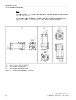
Страница 43: ...4 40f 43 3 2 1 Transporting Information will be provided in this chapter on how to correctly lift and transport the motors Figure 3 1 Lifting and transporting the motor with a cross beam example Horizontal shaft extension standard Shaft extension pointing downwards Figure 3 2 Location of the lifting eyebolts on 1PH808 ...

Страница 44: ...olts cannot always be attached at the DE without collision For this reason the lifting eyebolts are already mounted on these motors as shown in the right hand part of the diagram Arrangement of the lifting eyebolts for 1PH808 Horizontal shaft extension standard Shaft extension pointing upwards Shaft extension pointing downwards Figure 3 3 Location of the lifting eyebolts on 1PH810 ...

Страница 45: ...d shields 3 2 2 Storage Note Replacing roller bearings Even if the motor was stored for more than three years under favorable conditions i e in a dry dust free room that is not susceptible to vibration you must replace the bearings If the motor was stored under unfavorable conditions you must replace the bearings after approx 18 months NOTICE Seizure damage to bearings If the motors are stored inc...

Страница 46: ...ion You are advised to rotate the shaft extension manually every three months Protection against humidity If a dry storage area is not available the following measures must be taken Wrap the motor in humidity absorbent material and then wrap it in film so that it is air tight Include several bags of desiccant in the seal tight packaging Check the desiccant and replace as required Place a humidity ...

Страница 47: ...17 610 48004 40f 47 Protecting the cooling water system When the units are delivered the stainless steel cast iron cooling water pipe system is not filled with cooling water When you place the motor in storage after use drain the cooling water ducts and purge them with air so that they are completely empty ...

Страница 48: ...Preparations for use 3 2 Transportation and storage 1PH808 1PH810 main motors 48 Operating Instructions 04 2017 610 48004 40f ...

Страница 49: ... Technical data on the motor enclosure Observe the technical data on the rating plate type plate on the motor enclosure The following must be taken into account when the motors are installed Observe the type of construction and degree of protection stamped on the rating plate and check that they comply with the conditions at the installation location Refer to the configuration manual for the permi...

Страница 50: ...ors must be installed in such a way that the cooling air can flow in and out without any obstruction and that the minimum distance s is maintained between the air inlet and discharge openings and adjacent components see Minimum distance diagram in Cooling section It is not permissible that the hot air is drawn in again Note Covers attached to the motor You must remount the covers for air cooled mo...

Страница 51: ...B3 or IMB35 with mounting feet must be mounted on flat surfaces with a planeness specification of 0 15 mm If the motor needs to be aligned locate metal shims below the motor feet in order to prevent the motor from being subject to any strain The number of shims should be kept as low as possible i e stack as few as possible Mounting using the motor flange flange mounting Note Flange mounting When t...

Страница 52: ...15 24 Flange mounting M10 10 d2 18 42 Use screws of property class 8 8 or higher Table 4 2 Tightening torques for foot flange mounting 1PH810 Retaining type Screw ISO 4017 Washer ISO 7092 Tightening torque 10 Nm Foot mounting M10 10 d2 18 42 Flange mounting M12 12 d2 20 70 Use screws of property class 8 8 or higher Alignment accuracy for coupling output The maximum permissible concentricity deviat...

Страница 53: ...alanced to balance quality grade G2 5 to ISO 1940 Rotary forces that exceed this are not permissible Note that rotary forces can also occur with coupling output If the output element is shorter than the feather key with balancing method H the section of the feather key that protrudes from the shaft contour and output element must be removed to maintain the balance quality Fit remove the output ele...

Страница 54: ...g the centering in the shaft extension Motor without output element WARNING Danger to life if feather keys are flung out The feather key in a shaft is only secured during transport to prevent it from falling out An open feather key sitting in the shaft will be flung out in operation Death or serious injury can result Remove an open feather key sitting in the shaft or secure it so that it cannot be...

Страница 55: ...n that the lubricating film is not optimally distributed until the motor has been in operation for a significant period of time i e up to 30 hours Before installing the motor run in the bearings This must be done for new motors for motors that have been in transport for a long time for motors that have been in storage for a long time Bearing noise will occasionally be audible during bearing run in...

Страница 56: ...e assembly i e spindle with mounted coupling half on a suitable fixture Residual imbalance u G1 g mm 4 Install the spindle in the headstock You need to align the location flange for the motor centering shoulder to ensure that the motor shaft and spindle shaft are precisely aligned Make sure that the radial axial runout deviation does not exceed 0 01 mm For centering the motor we recommend a G6 fit...

Страница 57: ...f on the motor shaft 6 Balance complete assembly i e motor with mounted coupling half Balance the motor when it is completely assembled with the coupling half The aim is to achieve the same vibration levels as the motor would exhibit without the coupling half Perform complete balancing as described in Chapter Balancing for Premium Performance bearing version Page 60 ...

Страница 58: ...k The coupling must exhibit an axial clearance of between 1 5 and 2 5 mm in order to prevent constraining forces exerted by the motor spindle assembly 8 Check the smooth running performance of the complete drive train To ensure satisfactory smooth running and a long bearing service life the specified vibration velocity values must not be exceeded at any point along the train ...

Страница 59: ...ons 04 2017 610 48004 40f 59 9 Balance the complete drive train The complete drive train will need to be balanced if the specified vibration velocity values cannot be achieved 1PH8 motor Location flange for motor Coupling reference dimension Spindle holder spindle housing Rotex GS clamping ring hubs steel Spindle ...

Страница 60: ...th special vibration severity Mounting a coupling element on the shaft extension changes the rotor balancing state As a consequence after mounting coupling elements the rotor must be completely balanced The following description shows using an example the procedure for 1PH8 motors with Premium Performance bearing version You must determine the vibration severity and the position of the imbalance b...

Страница 61: ...al approach 1 Prepare to make the reference measurement Freely suspended the motor according to IEC 60034 14 The natural frequency of the motor spring system must be less than 3 Hz As a consequence use springs that are adapted to the motor mass The motor must be freely suspended so that the reference measurement can provide a correct measurement result ...

Страница 62: ...2017 610 48004 40f 2 Make a reference mark on the shaft DE for the speed and angle detection 3 Position the measuring sensors Sensor 1 for the DE sensor 2 for the NDE 4 Perform the reference measurement on the freely suspended motor for the DE and the NDE Measure the absolute value and angular position of the imbalance 1st order ...

Страница 63: ...08 1PH810 main motors Operating Instructions 04 2017 610 48004 40f 63 5 Attach the coupling to the shaft extension DE 6 Perform the measurement on the coupled motor for the DE and the NDE Also in this case measure the absolute value and angular position of the imbalance 1st order ...

Страница 64: ... screw one or several balancing screws into the rotor Start at the side with the highest absolute imbalance For instance if you detect an imbalance at the DE at an angle of 175 then you must screw in a balancing screw on the opposite side at an angle of 355 175 180 355 8 It may be necessary to repeat Point 6 and Point 7 several times until the imbalance has been completely removed ...

Страница 65: ...n and a long service life the vibration values specified to ISO 10816 must not be exceeded at the defined measuring points on the motor Table 4 3 Max permissible radial vibration values1 Vibration frequency Vibration values 6 3 Hz Vibration displacement s 0 16 mm 6 3 250 Hz Vibration velocity vrms 4 5 mm s 250 Hz Vibration acceleration a 10 m s2 1 Both values must be maintained simultaneously Tabl...

Страница 66: ...pment must fulfill the requirements of ISO 2954 The vibration acceleration must be measured as a peak value in the time range in a frequency band of 10 to 2000 Hz If appreciable vibration excitation in excess of 2000 Hz e g gear teeth meshing frequencies can be expected the measurement range must be adapted accordingly This does not alter the maximum permissible values ...

Страница 67: ... rotating unions are made up of two separate parts the rotating part with a mechanical seal and the static part with a mechanical seal and supply connection By eliminating the bearings higher speeds can be achieved and the rotating union is less sensitive to vibrations and lateral loads However an adapter such as is described in Ch Suggestion for an adapter for bearingless frame supported rotating...

Страница 68: ...ine does not lead downward the leakage can flood the rotating union and the motor This can result in failure of the rotating union and motor To ensure the leakage is led away the leakage line must always lead downward so that nothing can flow back When mounting ensure that the leakage line always leads downward NOTICE Axial forces due to coolant pressure Coolant under high pressure usually 40 to 9...

Страница 69: ...ading force Fc This reduces or even eliminates the preloading force of the motor bearing For bearingless frame supported rotating unions axial forces can also arise depending on the internal differing hole diameters These act against the forces from the joint so they have a smaller effect on the bearing preloading force Ensure that the axial forces from the rotating union are greater than those fr...

Страница 70: ...in Chapter Radial and axial forces apply The axial forces that act in the rotating union must be requested from the manufacturer Hollow shaft version Table 4 5 Hollow shaft version 1PH808 1PH810 Thread on DE M12 x 1 25 RH M16 x 1 5 RH Centering on DE 16H7 20H7 Thread on NDE M12 x 1 25 LH M16 x 1 5 LH Centering on NDE 14 0 008 0 001 18 0 007 0 003 Through hole 8 11 5 Key surface NDE SW19 SW27 4 7 1...

Страница 71: ... motors Water cooled motors have a 2 in the 11th position in the Article No With water cooled motors you can mount the rotating union directly on the motor Use rotating unions with radial or axial connections Mounting rotor supported rotating union on water cooled motors Sealing cover Balancing disk Rotor supported rotating union e g DEUBLIN 1109 020 188 Leakage hose Inlet hose ...

Страница 72: ...an intermediate housing between the motor and the axially mounted fan The intermediate housing is used to accommodate the rotating union The intermediate housing is suitable for rotating unions with the following dimensions Length up to 120 mm without rotor connection thread and centering Diameter up to 55 mm Due to limitations of space rotating unions with radial connections are advisable for air...

Страница 73: ...rs Operating Instructions 04 2017 610 48004 40f 73 Mounting rotor supported rotating unions on air cooled motors Sealing cover Balancing disk Intermediate housing Rotor supported rotating union e g DEUBLIN 1109 020 188 Cutout Cover openings for connections must be closed again Leakage hose Inlet hose Fan ...

Страница 74: ...inlet and leakage to the rotating union Use angle elements if necessary Note Rotating union to be used Use a rotating union with radial connections 4 Screw the rotating union into the NDE motor shaft extension Tighten the rotating union with the correct tightening torque For this use the wrench grip surface on the NDE motor shaft extension to hold the other side 5 Position the rotating union horiz...

Страница 75: ...pose the dimensions of the manufacturer of the rotating union must be complied with The adapter should be designed as shown in Chapter Suggestion for an adapter for bearingless frame supported rotating unions The gap between the adapter and the NDE shaft extension in the radial direction must be as small as possible approx 0 25 mm and be as long as possible in the axial direction so that exiting c...

Страница 76: ...d the balancing disk If the motor is mounted vertically all 6 drainage holes should be opened if the motor is mounted horizontally it is enough to open the two lower drainage holes Note It is advantageous to provide a sealing air connection to protect the motor from penetration of coolant The diameters and end faces of the adapter for supporting the encoder cover or the static part of the rotating...

Страница 77: ... No together with option Y64 Rotating unions with radial or axial connections can be used Mounting a bearingless rotating union on a water cooled motor 1 Encoder cover 2 Balancing disk 3 Adapter 4 6 x M5 bolts 5 Rotating part of the rotating union e g DEUBLIN 1129 050 301 6 Static part of the rotating union e g DEUBLIN 1129 050 301 7 Leakage hose min diam 12mm inside 8 Leakage hose as backup and f...

Страница 78: ...or rotating unions up to a length without rotor connection thread and centering of 120 mm and a diameter of up to 55 mm Due to limitations of space rotating unions with radial connections are recommended for air cooled motors e g DEUBLIN 1129 050 301 Rotating unions with axial connections are also possible in short versions e g DEUBLIN 1129 730 731 In that case an angled element must be used on th...

Страница 79: ...oled motor 1 Encoder cover 8 Leakage hose as backup and for faults 2 Balancing disk 9 Inlet hose 3 Adapter 10 Sealing air connection 4 6 x M5 bolts 11 Intermediate housing 5 Rotating part of the rotating union e g DEUBLIN 1129 050 301 12 Cutout 6 Static part of the rotating union e g DEUBLIN 1129 050 301 13 Cover openings for connections must be closed again 7 Leakage hose min internal diam 12 mm ...

Страница 80: ...delivery on the encoder cover with 6x M5 screws Position the adapter in such a way that the leakage connection is at the lowest point with horizontal mounting 6 Mount the hoses for leakage and sealing air on the adapter if necessary using angled elements 7 Mount the hose for the supply to the static part of the rotating union if necessary using angled elements 8 Screw the static part onto the adap...

Страница 81: ...nted Keep rotating unions free of chips and burrs Position the rotating union horizontally in such a way that the leakage connection is at the lowest point Always route the leakage hose downward at at least 15 with a large cross section If the leakage hose is higher than the leakage connection and the mechanical seal is open the rotating union and possibly also the motor will be flooded The motor ...

Страница 82: ...ing of rotating unions on 1PH8 hollow shaft motors 1PH808 1PH810 main motors 82 Operating Instructions 04 2017 610 48004 40f Intermediate housing for air cooled motors Cutout for hoses to be made by the customer Motor side Fan side ...

Страница 83: ... 16 16 D 170 185 4 7 4 Suggestion for an adapter for bearingless frame supported rotating unions Note Comply with the manufacturer s specifications Comply with the specifications and instructions provided by the manufacturer when installing the rotating union Figure 4 5 Example of the version of an adapter for supporting the static part of a bearingless frame supported rotating union 1PH808 1PH810...

Страница 84: ...Mechanical mounting 4 7 Mounting of rotating unions on 1PH8 hollow shaft motors 1PH808 1PH810 main motors 84 Operating Instructions 04 2017 610 48004 40f ...

Страница 85: ... the bearing shield 1 Make sure that the cooling water fulfills the required cooling water specification see the chapter titled Cooling 2 Make sure that the appropriate volume of cooling water is available see the rating plate type plate 3 Screw the cooling water pipes into the female thread You can connect the inlet and outlet as required 4 Ensure that the maximum permissible operating pressure d...

Страница 86: ...omponents that can be damaged destroyed by electrostatic discharge ESDS Encoder systems and temperature sensors are components that can be destroyed by electrostatic discharge ESD Components that are sensitive to electrostatic discharge can be damaged if you touch the connections with your hands or with electrostatically charged tools Carefully observe the information in Chapter Handling electrost...

Страница 87: ...use parallel connecting cables if necessary Make sure that the inside of the terminal box or connector is clean and free of cable cuttings and moisture Tighten all of the screws for the electrical connections terminal board connections with the exception of the terminal strips to the specified torque Table 5 1 Tightening torques Thread M4 M5 M6 M8 M10 Tightening torque Nm 0 8 1 2 1 8 2 5 2 7 4 5 5...

Страница 88: ...the lid of the terminal box Figure 5 1 Circuit diagram NOTICE Cable damage caused by inappropriately changing the cable outlet direction You will damage connecting cables if you inappropriately change the cable outlet direction The direction of the cable outlet must not be changed as this invalidates warranty claims 5 2 3 Terminal box Assign the terminals in the terminal box as shown in the diagra...

Страница 89: ...ions 04 2017 610 48004 40f 89 Terminal screw M5 Grounding screw M5 Insulation strips Figure 5 2 Terminal box gk803 3 pole for 1PH808 M5 connecting studs Grounding screw M5 Insulation strips Jumper Figure 5 3 Terminal box gk806 6 pole can be switched between star and delta for 1PH808 ...

Страница 90: ...otors 90 Operating Instructions 04 2017 610 48004 40f Terminal screw M5 Grounding screw M5 Insulation strips Figure 5 4 Terminal box gk813 3 pole for 1PH810 Terminal screw M5 Grounding screw M5 Insulation strips Figure 5 5 Terminal box gk823 3 pole for 1PH810 ...

Страница 91: ...lation strips Jumper Figure 5 6 Terminal box gk826 6 pole can be switched between star and delta for 1PH810 Terminal screw M6 Grounding screw M6 Insulation strips Figure 5 7 Terminal box gk803 1PH808 gk823 1PH810 3 pole cable entry DE Note Cable exit direction DE The motor with the cable exit direction DE has a D in the 15th position of the Article No ...

Страница 92: ...r circuit or as a fixed configuration in terminal box gk806 for 1PH808 and in terminal box gk826 for 1PH810 Standard configuration star connection via jumpers Figure 5 8 Fixed star delta connection in the terminal box 5 2 4 Power connector Use connector size 1 5 Assign the connector as shown in the Power connector diagram Connect the protective conductor Figure 5 9 Power connector view of connecto...

Страница 93: ...2 Depending on design of metric cable gland 3 Current carrying capacity based on EN 60204 1 and IEC 60364 5 52 routing type E Table 5 3 1PH8 motors shaft height 100 Terminal box type Cable entry power Cable entry external signals Max external cable diameter 2 Number of main terminals Max cross section per terminal Max cur rent per terminal 3 gk813 1 x M32 x 1 5 1 x M16 x 1 51 24 2 mm Phases 3 x M5...

Страница 94: ...devices ESD Motors designed for SINAMICS drive systems are equipped with an internal Sensor Module which contains an encoder and temperature evaluation system as well as an electronic rating plate The Sensor Module is mounted instead of the signal connector and is equipped with a 10 pin RJ45plus socket This is known as a DRIVE CLiQ interface The pin assignment is independent of the motor internal ...

Страница 95: ...Q interface the speed encoder and temperature sensor are connected via a signal connector Motors that are not equipped with DRIVE CLiQ require a Sensor Module Cabinet Mounted SMC or a Sensor Module External SME when operated with SINAMICS S120 The motor is connected to the SMC or the SME via the signal cable The SMC or SME is connected to the Motor Module via a MOTION CONNECT DRIVE CLiQ cable Figu...

Страница 96: ...nnector is completely secure to avoid damaging the pin contacts 5 2 8 Connecting an HTL incremental encoder Encoder connection with terminal block using an additional terminal box Induction motors can be equipped with an additional terminal box This means that you can connect the following HTL incremental encoders for operation with a SINAMICS G via a terminal block HTL1024 S R and HTL2048 S R The...

Страница 97: ...an HTL incremental encoder Terminal Signal assignment 1 1R2 2 1R1 3 B 4 R 5 R 6 A 7 A 8 CTRL 9 B 10 M encoder 11 P encoder Note Additionally supplied sensors Connect the following additional sensors in the terminal box according to Chapter Terminal boxes Temperature sensor as a standby or PTC thermistor circuit for warning and shutdown Note Temperature sensor The type of temperature sensor is to b...

Страница 98: ...tor in the terminal box The motor grounding conductor cross section must be in full compliance with the installation regulation e g according to IEC EN 60204 1 The grounding conductor is connected in the terminal box Figure 5 15 Connecting the grounding conductor Equipotential bonding The motor design provides for internal equipotential bonding between the grounding terminal in the box enclosure a...

Страница 99: ...ng voltage current insulation material and load carrying capacity Before connecting the device make sure that the line voltage matches the device voltage Check whether the data on the fan rating plate matches the connection data Connection cables must not be subject to excessive tensile stress NOTICE Damage to the fan when inappropriately operated The fan can be destroyed if inappropriately operat...

Страница 100: ...04 2017 610 48004 40f 1 Connector size 1 with full thread 2 Connector SPEED CONNECT size 1 3 Terminal for the cable shield 4 Pin assignment 5 Circuit diagram 6 Cable shield 7 Conductor designation L1 N power cable 1 5 mm PE protective conductor Figure 5 16 1 phase connection of external fan ...

Страница 101: ...00 V 60 Hz 10 A 480 V 60 Hz 10 A NDE DE 0 12 0 09 0 12 DE NDE 0 13 0 09 0 13 Note the following information regarding connections Only use cables that comply with the relevant installation regulations regarding voltage current insulation material and load carrying capacity Before connecting the device make sure that the line voltage matches the device voltage Check whether the data on the fan rati...

Страница 102: ...itted and completely closed NOTICE Damage to the fan when inappropriately operated The fan can be destroyed if inappropriately operated Use blocking protection stall protection to protect the fan against inappropriate operation To do this use a suitable motor circuit breaker where all poles can be disconnected Operate the fan using this circuit breaker Provide an interlocking circuit that prevents...

Страница 103: ... Connector size 1 with full thread 2 Connector SPEED CONNECT size 1 3 Terminal for the cable shield 4 Pin assignment 5 Circuit diagram 6 Cable shield 7 Conductor designation U V W power cable 1 5 mm each cable separately shielded PE protective conductor Figure 5 18 3 phase connection of external fan via connector ...

Страница 104: ...ecting a holding brake option Electrically connecting a holding brake option is described in the Appendix Holding brake operating instructions See also Holding brake operating instructions Page 152 5 2 15 Sealing air connection option Q12 Cooling lubricants containing oil capable of creepage which can also be corrosive are mainly used for machine tools and transfer machines For critical applicatio...

Страница 105: ...nt temperature Max inlet temperature C 40 Max residual water content g m 0 12 Max residual oil content g m 0 01 Max residual dust mg m 0 1 Min supply pressure Pa 2 0 x 105 Max supply pressure Pa 3 x 10⁵ Particle size for hollow shaft encoder μm 8 Particle size for optical encoders µm 3 Conditioning B Main drives with a shaft sealing ring Min inlet temperature C Ambient temperature Max inlet temper...

Страница 106: ...48004 40f Figure 5 19 Sealing air connection option Q12 Necessary sealing air volume Volume Nm h Nm standard cubic meter Approx 2 3 at 2 bar Note The volume data refers to the specified minimum supply pressure For higher supply pressures the flow rate increases corresponding to the motor flow resistance ...

Страница 107: ...motors to the line supply using residual current devices RCDs For line supplies with grounded line conductor e g TT line supplies use an isolating transformer with grounded neutral point on the secondary side between the line supply and the drive system so that the motor insulation is not overstressed When connected to IT line supplies a monitoring device must signal the first fault between an act...

Страница 108: ...death severe injury and material damage Never operate the motor without cooling Only commission the cooling water circuit when the motor is in a cool condition WARNING Danger to life when the forced ventilation draws in hair and articles of clothing There is a danger of being drawn into the machine by means of hair ties loose articles of clothing etc at the air intake Remove any ties or similar We...

Страница 109: ...stroyed Control the holding brake so that it can never be used as an operating brake The holding brake microswitch must be connected to the control and evaluated also refer to the supplementary sheet on the holding brake 4BZFM 100 It must be completely ruled out that the motor is operated with the holding brake closed It is only permissible to control the holding brake when the motor is at a stand...

Страница 110: ...ry components of the configured drive line up available correctly dimensioned installed and connected Are the manufacturer s documentation for the system components e g drive system encoder cooling system brake and the SIMOTICS M 1PH8 main motors Configuration Manual available If the 1PH8 motor is to be fed from a SINAMICS S120 drive system Is the following current SINAMICS documentation available...

Страница 111: ...ve the couplings been aligned and balanced Has the tension of a belt drive been correctly adjusted Have the gear tooth flank and gear tooth tip play as well as radial play been correctly adjusted for geared outputs Table 6 3 Checklist 3 checks regarding the electrical system Check OK Has the motor been connected so that it rotates in the specified direction Have the minimum insulation resistance v...

Страница 112: ...ctrical installation of the safety relevant components OK These include the installation of a circuit breaker and attaching protective guards Are the cable entry glands correctly sealed Are the fan air intake and the area around the fan blades free of foreign bodies Does the fan have the correct direction of rotation An arrow is stamped on the fan rating plate This arrow indicates the correct dire...

Страница 113: ...ng versions 10th position of the Article No require a 8 kHz pulse frequency Presently this value is not automatically set Further for these motors the current controller must be adapted These parameters are currently not saved in the DRIVE CLiQ interface data The commissioning engineer must manually adapt these parameters These motors may only be operated with a fast current controller p1810 11 ye...

Страница 114: ...he terminals when making measurements or immediately after the measurement Check the connected supply feeder cables to ensure that the line supply voltage cannot be connected Always measure the insulation resistance of the winding to the motor enclosure when the winding temperature is between 20 and 30 C When performing the measurement wait until the final resistance value is reached this takes ap...

Страница 115: ...itical resistance value 0 5 MΩ kV Example Critical resistance for a rated voltage VN of 0 6 kV 0 6 kV x 0 5 MΩ kV 0 3 MΩ Note Cleaning and or drying the windings when reaching critical insulation resistance If the critical insulation resistance is less than or equal to this value the windings must be dried or if the fan is removed cleaned thoroughly and dried Note that the insulation resistance of...

Страница 116: ...out this topic in the converter operating instructions Before switching on Ensure that the converter is correctly parameterized Use the appropriate commissioning tools e g Drive ES or STARTER Switch on the cooling system Switching on 1 Switch on the motor at the converter 2 Ensure smooth motor operation 3 Check the function of the motor cooling system 4 Check the function of the safety equipment 5...

Страница 117: ...when the motor is in a cool condition NOTICE Overheating because there is no cooling water If the cooling water supply fails or the motor is operated for a short time without cooling water this can cause it to overheat This can result in material damage or destroy the motor completely Never operate the motor without the cooling water supply Monitor the permissible water inlet temperatures Forced v...

Страница 118: ...Commissioning 6 6 Cooling 1PH808 1PH810 main motors 118 Operating Instructions 04 2017 610 48004 40f ...

Страница 119: ...nsure that nobody is at risk at switch on Before switching on check that there are no loose objects in or on the motor that can fall or can be flung off The motor is switched on at the converter Read about this topic in the converter operating instructions Operation While the motor is operational ensure that the specified parameters are maintained Make sure that The current drawn is in the specifi...

Страница 120: ... 40f NOTICE Motor damage caused by worn bearings Worn bearings cause motor damage Always comply with the bearing change intervals depending on the operating state Switching off The motor is switched off at the converter Read about this topic in the converter operating instructions ...

Страница 121: ...ith respect to normal operation or faults determine the cause using the Possible faults table If you have identified the cause attempt to resolve the fault using the Key fault causes and remedial measures table In this regard observe the relevant chapter in the documentation associated with the components of the complete drive system Table 7 1 Possible faults Fault Cause of fault see key table Mot...

Страница 122: ...ncorrectly connected Check winding connection I Heat dissipation obstructed by deposits Clean the drive surfaces Ensure that the cooling air can flow in and out unimpeded Cooling air inlet outlet is blocked by foreign bodies Remove the blockage Ensure that the cooling air can flow in and out unimpeded Fan motor does not start Check the function of the fan motor J Insufficient shielding for motor a...

Страница 123: ...at it remains dry e g appropriate drying agents When recommissioning after longer non operational periods of the motor perform the checks and measures listed in Chapter Commissioning Disconnect the motor from the cooling water system Remove any cooling water from the motor Blow out the cooling ducts with compressed air to dry them If the motor is not operational for extended periods of time run it...

Страница 124: ...Operation 7 2 Non operational periods 1PH808 1PH810 main motors 124 Operating Instructions 04 2017 610 48004 40f ...

Страница 125: ...emical burns and irritate the skin and mucous membranes Carefully observe all of the safety and application notes provided on the packaging of the cleaning agents and solvents Ensure that any vapors that are released are drawn out and that the work area is well ventilated Use the appropriate personnel protection equipment e g protective eyewear gloves respiration filter CAUTION Injuries caused by ...

Страница 126: ...ls General Inspect and maintain the motor at regular intervals to be able to identify faults at an early stage and remove them NOTICE Resulting damage to the machine Unusual conditions or faults of the motor e g overload or short circuit can result in consequential damage to the machine Immediately inspect the motor if faults or exceptional conditions occur Cleaning Regularly clean the drive syste...

Страница 127: ...d that the required cooling water quality is ensured Cooling water system water cooling 8 1 3 Initial inspection Carry out a first inspection after installation 500 operating hours at the latest after 6 months corrective maintenance of the motor Note Adapt the inspection to the plant specific conditions Further tests are also necessary in line with the component documentation or corresponding to t...

Страница 128: ... mounting bolts screws for the mechanical and electrical connections are tight the insulation resistance of windings lies in the permissible tolerance range any bearing insulation is fitted in accordance with the labeling cables and insulating parts and components are in a good condition and are not discolored the permissible radial forces cantilever forces of the roller bearings are complied with...

Страница 129: ...bration and surge loads frequent reversing operation Table 8 2 Bearing version maximum speeds and bearing replacement intervals Shaft height Bearing version Maximum speed nmax rpm Average operating speed nm rpm Statistical bearing life time L10h h Recommended bearing replacement interval tLW h Permanent lubrication Relubrication 80 Standard with locating bearing 10000 8000 20000 20000 Standard wit...

Страница 130: ...rformance 20000 8000 8000 100 Option L37 10000 8000 8000 Performance 12000 8000 8000 High Performance 18000 8000 8000 Note 1PH8 motors require special bearings which can be obtained via the Siemens Service Center 8 1 6 Premium Performance bearing version Table 8 4 Premium Performance bearing version maximum speed and bearing change intervals Shaft height Maximum speed nmax rpm Average operating sp...

Страница 131: ...hen continually operating with nmax the sealing air is permanently switched on Sealing air connection and conditioning see Chapter Sealing air connection option Q12 Note Difficult operating conditions Under difficult operating conditions the bearing replacement intervals tLW are reduced by up to 50 Difficult operating conditions include continuous operation with nmax high vibration and surge loads...

Страница 132: ...h off the external cooling unit Disconnect the external cooling unit circuit and lock out the external cooling unit so that it cannot be switched on again If at all possible lock the fan blades so that they cannot rotate 1 Switch off the motor and external cooling unit 2 Disconnect both of them from the power supply by disconnecting all phases 3 Ensure that they both cannot be accidentally switche...

Страница 133: ...g agents and solvents can cause chemical burns and irritate the skin and mucous membranes Carefully observe all of the safety and application notes provided on the packaging of the cleaning agents and solvents Ensure that any vapors that are released are drawn out and that the work area is well ventilated Use the appropriate personnel protection equipment e g protective eyewear gloves respiration ...

Страница 134: ...guard with fan back onto the cooling unit To do so for 1PH808 tighten 4 screws and for the 1PH810 6 screws with a torque of 3 8 Nm 0 6 Nm 5 Check that you have removed all cleaning equipment and cleaning agents 6 Check that you have re attached any parts that were removed for cleaning 7 Reconnect the power supply 8 Switch on the motor and external cooling unit again 8 1 8 Replacing an encoder When...

Страница 135: ...e sensors are components that can be destroyed by electrostatic discharge ESD Components that are sensitive to electrostatic discharge can be damaged if you touch the connections with your hands or with electrostatically charged tools Carefully observe the information in Chapter Handling electrostatic sensitive devices ESD The Siemens Service Center Bad Neustadt Germany should be contacted when ca...

Страница 136: ...Mounting Do not reuse rolling contact bearings that have been removed Heat up the new rolling contact bearings evenly to 80 100 C and attach them When doing so make sure that the bearing inner ring lies on the shaft shoulder The device must not be subject to hard knocks e g do not use a hammer etc Insert the motor rotor into the stator Secure the bearing cap Insert the NDE bearing with shaft sprin...

Страница 137: ...ct bearings to run in to distribute the grease evenly When doing so the motors should be initially run continuously from 0 to approx 75 of the maximum speed nmax over a period of 15 minutes 8 2 2 Removing installing the speed encoder Note Removing installing the encoder Unscrew the terminal box cover and disconnect the power cables Unscrew the external fan unit if installed and the encoder cover ...

Страница 138: ...nce 1PH808 1PH810 main motors 138 Operating Instructions 04 2017 610 48004 40f 1 Screw 5 Encoder shaft 2 Connector cover 6 Screws 3 Motor shaft 9 xx See section Spare parts 4 Jacking thread Figure 8 2 Motor shaft encoder shaft connection ...

Страница 139: ...and secure in place e g with Loctite 243 Observe the distance between the torque bracket and encoder this step does not need to be carried out if the encoder is already mounted 2 If necessary remove the threaded pin used earlier to remove the encoder 3 Unscrew the screw 1 for the replacement encoder 4 Remove the connector cover 2 for the replacement encoder Place the encoder with torque bracket 9 ...

Страница 140: ...el encoder The toothed wheel encoder has the following description without the DRIVE CLiQ interface Incremental encoder sin cos 1 Vpp 256 S R without C and D tracks encoder IN256 S R The marking is 1PH8 C The toothed wheel encoder has the following description with the DRIVE CLiQ interface Incremental encoder 19 bit without commutation position encoder IN19DQ The marking is 1PH8 S ...

Страница 141: ... 1PH810 main motors Operating Instructions 04 2017 610 48004 40f 141 1 Screws 2 Cover 8 Connector 3 Balancing weight 9 Screws 4 Screws 10 Scanning unit 5 Cover 11 Toothed wheel 6 Screw 12 Motor shaft Figure 8 3 Installing the toothed wheel encoder ...

Страница 142: ... motor shaft 12 and allow it to cool down 2 Lock the screws 9 for attaching the scanning unit 10 e g with Loctite 243 3 Observe the mounting dimensions see Fig Installing the toothed wheel encoder 8 2 4 Replacing the DRIVE CLiQ interface encoder module WARNING Danger to life when using an incorrect encoder module The DRIVE CLiQ encoder contains motor and encoder specific data and an electronic typ...

Страница 143: ...omponents or terminal box parts screwed onto the stator housing the following tightening torques apply depending on the thread size with a tolerance of 10 property class 8 8 and 8 or higher to DIN ISO 898 Table 8 5 Tightening torque for screwed connections Thread diameter M4 M5 M6 M8 M10 M12 M16 Tightening torque Nm 3 5 9 24 42 70 165 Bolt locking devices Nuts or bolts that are mounted together wi...

Страница 144: ...Maintenance 8 2 Corrective maintenance 1PH808 1PH810 main motors 144 Operating Instructions 04 2017 610 48004 40f ...

Страница 145: ...or you to determine the article numbers of standard spare parts and parts kits for motors Simply enter the the article number machine type and serial number at www siemens com sow 1 00 DE bearing assembly complete 1 01 Bearing cap 1 02 Screw 1 03 USIT washer 1 04 O ring 1 05 Cover 1 06 Grease slinger 1 07 Roller bearings 1 08 Screw 6 00 NDE bearing assembly complete 6 02 Roller bearings 6 03 Screw...

Страница 146: ...der kit for the individual encoder version solid shaft 9 01 Encoders 9 04 O ring 9 05 Screw 9 06 Torque bracket 9 07 Screw Encoder kit for hollow shaft encoders not in diagram Replacement parts example Measuring wheel O ring Sensor head DRIVE CLiQ interface not in diagram Replacement parts example ...

Страница 147: ...Spare parts 1PH808 1PH810 main motors Operating Instructions 04 2017 610 48004 40f 147 Figure 9 1 Spare parts example ...

Страница 148: ...Spare parts 1PH808 1PH810 main motors 148 Operating Instructions 04 2017 610 48004 40f ...

Страница 149: ...oil water 5 Remove all cables 6 Remove the fixing elements from the motor 7 Transport the motor to a suitable location for disassembly Also observe the notes provided in Chapter Maintenance Dismantle the motor using the general motor typical procedures WARNING Danger to life caused by falling machine parts The machine partially comprises heavy individual components When removing the machine these ...

Страница 150: ...or recycling according to whether they are Electronics waste e g sensor electronics Iron to be recycled Aluminum Non ferrous metal e g motor windings Insulating materials Process materials and chemicals Sort the process materials and chemicals for recycling according to whether they are Oil Dispose of the spent oil as special waste in accordance with the spent oil ordinance Grease Solvents Cleaner...

Страница 151: ...or Note UL certification The holding brakes are not UL approved Motors with mounted brake therefore do not have the cUR marking Notes on operation are provided in the operating instructions provided Note Maintenance and corrective maintenance Maintenance and corrective maintenance must only be carried out by personnel that have been appropriately authorized by Siemens See also Properties Page 35 ...

Страница 152: ...Appendix A 2 Holding brake operating instructions 1PH808 1PH810 main motors 152 Operating Instructions 04 2017 610 48004 40f A 2 Holding brake operating instructions ...

Страница 153: ...Appendix A 2 Holding brake operating instructions 1PH808 1PH810 main motors Operating Instructions 04 2017 610 48004 40f 153 ...

Страница 154: ...Appendix A 2 Holding brake operating instructions 1PH808 1PH810 main motors 154 Operating Instructions 04 2017 610 48004 40f ...

Страница 155: ...Appendix A 2 Holding brake operating instructions 1PH808 1PH810 main motors Operating Instructions 04 2017 610 48004 40f 155 ...

Страница 156: ...Appendix A 2 Holding brake operating instructions 1PH808 1PH810 main motors 156 Operating Instructions 04 2017 610 48004 40f ...

Страница 157: ...Appendix A 2 Holding brake operating instructions 1PH808 1PH810 main motors Operating Instructions 04 2017 610 48004 40f 157 ...

Страница 158: ...Appendix A 2 Holding brake operating instructions 1PH808 1PH810 main motors 158 Operating Instructions 04 2017 610 48004 40f ...

Страница 159: ...Appendix A 2 Holding brake operating instructions 1PH808 1PH810 main motors Operating Instructions 04 2017 610 48004 40f 159 ...

Страница 160: ...Appendix A 2 Holding brake operating instructions 1PH808 1PH810 main motors 160 Operating Instructions 04 2017 610 48004 40f ...

Страница 161: ...Appendix A 2 Holding brake operating instructions 1PH808 1PH810 main motors Operating Instructions 04 2017 610 48004 40f 161 ...

Страница 162: ...Appendix A 2 Holding brake operating instructions 1PH808 1PH810 main motors 162 Operating Instructions 04 2017 610 48004 40f ...

Страница 163: ...Appendix A 2 Holding brake operating instructions 1PH808 1PH810 main motors Operating Instructions 04 2017 610 48004 40f 163 ...

Страница 164: ...Appendix A 2 Holding brake operating instructions 1PH808 1PH810 main motors 164 Operating Instructions 04 2017 610 48004 40f ...

Страница 165: ...Appendix A 2 Holding brake operating instructions 1PH808 1PH810 main motors Operating Instructions 04 2017 610 48004 40f 165 ...

Страница 166: ...Appendix A 2 Holding brake operating instructions 1PH808 1PH810 main motors 166 Operating Instructions 04 2017 610 48004 40f ...

Страница 167: ...Appendix A 2 Holding brake operating instructions 1PH808 1PH810 main motors Operating Instructions 04 2017 610 48004 40f 167 ...

Страница 168: ...Appendix A 2 Holding brake operating instructions 1PH808 1PH810 main motors 168 Operating Instructions 04 2017 610 48004 40f ...

Страница 169: ...Appendix A 2 Holding brake operating instructions 1PH808 1PH810 main motors Operating Instructions 04 2017 610 48004 40f 169 ...

Страница 170: ...Appendix A 2 Holding brake operating instructions 1PH808 1PH810 main motors 170 Operating Instructions 04 2017 610 48004 40f ...

Страница 171: ...Appendix A 2 Holding brake operating instructions 1PH808 1PH810 main motors Operating Instructions 04 2017 610 48004 40f 171 ...

Страница 172: ...Appendix A 2 Holding brake operating instructions 1PH808 1PH810 main motors 172 Operating Instructions 04 2017 610 48004 40f ...

Страница 173: ...Appendix A 2 Holding brake operating instructions 1PH808 1PH810 main motors Operating Instructions 04 2017 610 48004 40f 173 ...

Страница 174: ...Appendix A 2 Holding brake operating instructions 1PH808 1PH810 main motors 174 Operating Instructions 04 2017 610 48004 40f ...

Страница 175: ...Appendix A 2 Holding brake operating instructions 1PH808 1PH810 main motors Operating Instructions 04 2017 610 48004 40f 175 ...

Страница 176: ...Appendix A 2 Holding brake operating instructions 1PH808 1PH810 main motors 176 Operating Instructions 04 2017 610 48004 40f ...

Страница 177: ...Appendix A 2 Holding brake operating instructions 1PH808 1PH810 main motors Operating Instructions 04 2017 610 48004 40f 177 ...

Страница 178: ...Appendix A 2 Holding brake operating instructions 1PH808 1PH810 main motors 178 Operating Instructions 04 2017 610 48004 40f ...

Страница 179: ...Appendix A 2 Holding brake operating instructions 1PH808 1PH810 main motors Operating Instructions 04 2017 610 48004 40f 179 ...

Страница 180: ...Appendix A 2 Holding brake operating instructions 1PH808 1PH810 main motors 180 Operating Instructions 04 2017 610 48004 40f ...

Страница 181: ...Appendix A 2 Holding brake operating instructions 1PH808 1PH810 main motors Operating Instructions 04 2017 610 48004 40f 181 ...

Страница 182: ...Appendix A 2 Holding brake operating instructions 1PH808 1PH810 main motors 182 Operating Instructions 04 2017 610 48004 40f ...

Страница 183: ...re sensor 98 Connection 85 Corrective maintenance 135 D Degree of protection 27 F Faults 121 Flange mounting 51 Foot mounting 51 Forced ventilation 32 G Gamma ring 136 H Holding brake option Connecting 104 Mounting 39 143 Removal 143 Holding brakes 36 Hotline 7 I Inspection and maintenance 126 M Maintenance intervals 126 Mounting the motor 51 N Nameplate 29 Noise emission 28 Non operational period...

Страница 184: ...20 Transportation 42 Sealing air connection 104 Siemens Service Center 7 Spare parts 145 Storage 45 T Technical Support 7 Terminal box 88 Tightening torques Electrical connections 87 Foot flange mounting 52 Screwed union connections 143 Training 7 Transportation 43 Types of construction 31 U Use for the intended purpose 23 V Vibration strength 65 Vibration values 65 W Water cooling 33 ...

Страница 185: ......

Страница 186: ......

Отзывы: