Description
2.4 Structure
1PH808/1PH810 main motors
38
Operating Instructions, 04/2017, 610.48004.40f
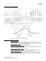
Coil current [A]: Current to release the brake.
Release time [ms]: Separating time until the brake releases (the specified values refer to the
maximum braking torque and rated voltage).
Engaging time [ms]: Connecting time until the brake engages according to the diagram
"Terminology (time) for holding operation" (The values refer to the maximum braking torque
and rated voltage).
Use for the intended purpose
“Spring-applied single-disk brake modules" are for mounting on induction or synchronous
motors and intended for use in commercial or industrial systems. It is prohibited to use the
brake in hazardous areas and zones or areas with firedamp. The externally mounted spring-
applied single-disk brake (electromagnetically released system) is designed as a holding
brake. Occasional emergency stop operations are possible.
WARNING
Danger to life when incorrectly using the holding brake
If you incorrectly use the holding brake, e.g. you use it as safety brake, this can lead to
severe accidents with personal injury and/or material damage.
•
Depending on the particular application, observe the corresponding accident prevention
regulations.
NOTICE
Irreversible reduction of the braking effect
The braking effect can be irreversibly reduced if you do not observe the permissible number
of braking operations per hour and/or the maximum permissible operating energy per hour.
Further, this can have a negative impact on the function of the holding brake.
•
When setting up machines and systems (when using the jog mode), observe the
information provided in the Table "Technical data of holding brakes".
•
The holding brake can be equipped with a manual release to remove the holding torque.
NOTICE
Inadvertent actuation of the holding brake
Material damage can occur if you inadvertently actuate (release) the holding brake.
•
Secure the holding brake against inadvertent actuation and misuse. The mechanical
manual brake release must always be in the center position when not actuated (see the
diagram “Spring-applied single-disk brake module"). Only then is the brake completely
engaged, and it is ensured that the spring-applied single-disk brake module can provide
its full braking effect.
•
You can remove the manual release lever. Observe the specific system-related
regulations, e.g. in the crane construction area relating to whether manual release is
permissible.
•
The rated operating conditions refer to DIN VDE 0580: 1994-10. The degree of
protection refers to DIN VDE 0470, part 1. Coordinate possible special measures with
the manufacturer if deviations exist.
Содержание SIMOTICS M-1PH8
Страница 1: ......
Страница 2: ......
Страница 8: ...Introduction 1PH808 1PH810 main motors 8 Operating Instructions 04 2017 610 48004 40f ...
Страница 12: ...Table of contents 1PH808 1PH810 main motors 12 Operating Instructions 04 2017 610 48004 40f ...
Страница 40: ...Description 2 4 Structure 1PH808 1PH810 main motors 40 Operating Instructions 04 2017 610 48004 40f ...
Страница 118: ...Commissioning 6 6 Cooling 1PH808 1PH810 main motors 118 Operating Instructions 04 2017 610 48004 40f ...
Страница 124: ...Operation 7 2 Non operational periods 1PH808 1PH810 main motors 124 Operating Instructions 04 2017 610 48004 40f ...
Страница 144: ...Maintenance 8 2 Corrective maintenance 1PH808 1PH810 main motors 144 Operating Instructions 04 2017 610 48004 40f ...
Страница 147: ...Spare parts 1PH808 1PH810 main motors Operating Instructions 04 2017 610 48004 40f 147 Figure 9 1 Spare parts example ...
Страница 148: ...Spare parts 1PH808 1PH810 main motors 148 Operating Instructions 04 2017 610 48004 40f ...
Страница 185: ......
Страница 186: ......


