I/O configuration variants
4.5 Using single-channel switched I/O
CPU 410-5H Process Automation
System Manual, 09/2014, A5E31622160-AB
65
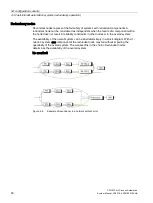
DP/PA link
The DP/PA link consists of one or two IM 153-2 interface modules, and one to five DP/PA
couplers that are either connected with one another via passive bus couplers or via bus
modules.
The DP/PA link creates a gateway from a PROFIBUS DP master system to PROFIBUS PA.
In this case the two bus systems are non-interacting through the IM 153-2 both physically
(galvanically) and in terms of protocols and time.
PROFIBUS PA can be connected to a redundant system via a DP/PA link. The following IM
157 PA coupler is supported: 6ES7 157-0AC83-0XA0
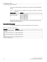
You can use the following DP/PA links:
DP/PA link
Article No.
ET 200M as DP/PA link with 6ES7 153–2BA82–0XB0
6ES7 153–2BA81–0XB0
6ES7 153–2BA70–0XB0
6ES7 153–2BA10–0XB0
6ES7 153–2BA02–0XB0
6ES7 153–2BA01–0XB0
Y Link
The Y Link consists of two IM 153-2 interface modules and one Y coupler that are connected
with one another by bus modules.
The Y Link creates a gateway from the redundant DP master system of an S7-400H to a
non-redundant DP master system. This means that devices with only one PROFIBUS DP
interface can be connected to a S7-400H as switched I/Os.
A single-channel DP master system can be connected to a redundant system via a Y
coupler.
The following IM 157 Y coupler is permissible: 6ES7 197-1LB00 0XA0.
You can use the following Y Links:
Y Link
Article No.
ET 200M as Y Link with
6ES7 153–2BA82–0XB0
6ES7 153–2BA81–0XB0
6ES7 153–2BA70–0XB0
6ES7 153–2BA10–0XB0
6ES7 153–2BA02–0XB0
6ES7 153–2BA01–0XB0
Rule for PROFIBUS DP
A single-channel switched I/O configuration must always be symmetrical.
●
This means, the fault-tolerant CPU and other DP masters must be installed in the same
slots in both subsystems (e.g., slot 4 in both subsystems)
●
The DP slaves must be connected to the same DP interface in both subsystems (e.g., to
the PROFIBUS DP interfaces of both fault-tolerant CPUs).

