


Connection examples for redundant I/Os
C.19 SM 322; DO 32 x DC 24 V/0,5 A, 6ES7 322–1BL00–0AA0
CPU 410-5H Process Automation
System Manual, 09/2014, A5E31622160-AB
355
C.19
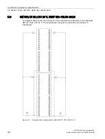
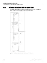
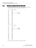
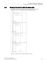
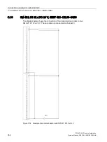
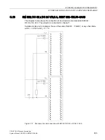
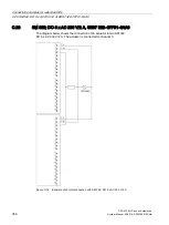
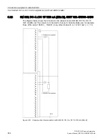
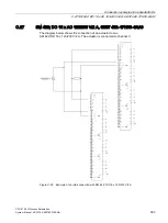
SM 322; DO 32 x DC 24 V/0,5 A, 6ES7 322–1BL00–0AA0
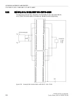
The diagram below shows the connection of an actuator to two redundant SM 322;
DO 32 x DC 24 V. The actuator is connected to channel 1.
Suitable diodes are, for example, those of the series 1N4003 ... 1N4007, or any other diode
with U
_r
>=200 V and I_
F
>= 1 A
Figure C-17 Example of an interconnection with SM 322; DO 32 x DC 24 V/0.5 A