System modifications during redundant operation
10.4 Removal of components
CPU 410-5H Process Automation
System Manual, 09/2014, A5E31622160-AB
173
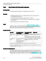
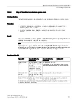
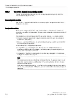
10.4.8
Removal of interface modules
Always switch off the power before you remove the IM460 and IM461 interface modules,
external CP 443-5 Extended DP master interface module, and their connecting cables.
Always switch off power to an entire subsystem. To ensure that this does not influence the
process, always set the subsystem to STOP before you do so.
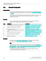
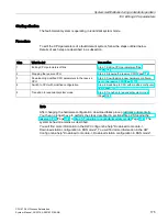
Procedure
1.
Change the hardware configuration offline (see section Step 1: Modify the hardware
configuration offline (Page 167))
2.
Modify and download the user program (see section Step 2: Modify and download the
user program (Page 168))
3.
Stop the reserve CPU (see section Step 3: Stop the standby CPU (Page 169))
4.
Download the new hardware configuration to the reserve CPU (see section Step 4:
Download new hardware configuration to the standby CPU (Page 169))
5.
Follow the steps below to remove an interface module from the subsystem of the reserve
CPU:
–
Switch off the power supply of the reserve subsystem.
–
Remove an IM460 from the central unit.
or
–
Remove an expansion unit from an existing chain.
or
–
Remove an external DP master interface module.
–
Switch on the power supply of the reserve subsystem again.
6.
Switch to CPU with altered configuration (see section Step 5: Switch to CPU with
modified configuration (Page 170))
7.
Proceed as follows to remove an interface module from the subsystem of the original
master CPU (currently in STOP mode):
–
Switch off the power supply of the reserve subsystem.
–
Remove an IM460 from the central unit.
or
–
Remove an expansion unit from an existing chain.
or
–
Remove an external DP master interface module.
–
Switch on the power supply of the reserve subsystem again.
8.
Change to redundant system mode (see section Step 6: Transition to redundant system


