


Brief description of ASM hardware
A.1 ASM 475
FC 45
A-4
Function manual, Release 03/2006 , J31069-D0167-U001-A2-7618
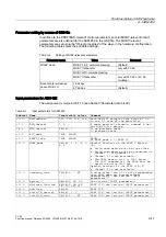
Interfaces and indicators of the ASM 475
6WDWXVDQGHUURULQGLFDWRUV
5HDGHUFRQQHFWLRQ
GLDJUDP7KHQXPEHUV
IRUWKHFRQQHFWLRQUHIHU
WRSOXJFRQQHFWRU;RQ
WKHWRSRIWKHKRXVLQJ
$60
:ULWHUHDGGHYLFH
b
:ULWHUHDGGHYLFH
b
7
7
5
5
7
7
5
5
6)
'&9
$&7B
(55B
35(B
5['B
$&7B
(55B
35(B
5['B
*7*$
02%<
SF:
System fault (hardware error on ASM)
DC 5 V:
24V are connected to ASM and the 5V on ASM
are okay.
ACT_1, ACT_2:
The corresponding write/read device is active in
processing an application command.
ERR_1, ERR_2:
A flashing pattern indicates the last error to occur.
This indicator can be reset with the parameter
option_1 (see Section "INPUT parameters").
PRE_1, PRE_2:
Indicates the application of an MDS.
RxD_1, RxD_2:
Indicates live communication with the write/read
device. May also indicate malfunctions on the
write/read device.