background image

Brief description of ASM hardware 


A.2 ASM 473 


FC 45 

A-6


Function manual, Release 03/2006 , J31069-D0167-U001-A2-7618 

A.2


A.2 

ASM 473 

$60BDGGUHVV


$60BFKDQQHO

0D[RI$60VFDQEH
RSHUDWHGLQRQH(7;


Figure A-2 

Maximum configuration of ASM 473 on an ET 200X with sample addressing 

 
Depending on the PROFIBUS master, up to 126 ET 200X modules can be run on one 

PROFIBUS branch. 

Hardware configuration 

The ASM 473 is integrated in the hardware configuration of the SIMATIC Manager by calling 

Setup.exe in the directory daten\S7_OM on the 

RFID Systems Software & Documentation 

CD. Currently, the ASM 473 cannot be integrated in masters of other manufacturers. 

Reader connection system 

A write/read device always occupies the two M12 connection sockets X3 and X4 on the ASM 

473. A prefabricated cable makes it easy to connect the write/read device. The standard 

model of the connection cable is 2 m in length. Other lengths are available on request. 
An SLG cable connector with screw-type terminals is available for users who want to make 

their own cables. Cables and SLG cable connectors can be ordered from the MOBY catalog. 

Содержание SIMATIC FC 45

Страница 1: ..._ ______________ ______________ Introduction 1 Description 2 Parameterizing 3 Commissioning 4 Error messages and troubleshooting 5 Examples applications 6 Brief description of ASM hardware A Programming the MOBY ASM on PROFIBUS B Service Support C SIMATIC Sensors RFID systems FC 45 Function manual Release 03 2006 J31069 D0167 U001 A2 7618 ...

Страница 2: ...oning and operation of a device system may only be performed by qualified personnel Within the context of the safety notes in this documentation qualified persons are defined as persons who are authorized to commission ground and label devices systems and circuits in accordance with established safety practices and standards Prescribed Usage Note the following Warning This device may only be used ...

Страница 3: ... 12 3 2 2 Command chaining 3 17 3 2 3 Command repetition 3 19 3 3 Presence check and MDS control 3 22 3 3 1 No MDS Control No Presence Check MDS_control 0 3 24 3 3 2 No MDS Control Presence Control with Field Scanning MDS_control 1 3 24 3 3 3 Field Scanning as MDS Control MDS_control 2 3 25 4 Commissioning 4 1 5 Error messages and troubleshooting 5 1 5 1 General errors 5 1 5 2 Error messages 5 2 6...

Страница 4: ...M 854 A 23 A 7 ASM 850 A 29 B Programming the MOBY ASM on PROFIBUS B 1 B 1 Programming the MOBY ASM on PROFIBUS DP V1 B 1 B 2 Cyclic Control Word between Master and MOBY ASM B 5 B 3 Methods of operation with the ASM B 8 B 4 Command and acknowledgement telegrams B 13 B 5 PROFIBUS implementation B 22 B 6 Example of a PROFIBUS Trace B 25 C Service Support C 1 C 1 Service Support C 1 C 2 Contacts C 1 ...

Страница 5: ...evice ON OFF 3 15 Table 3 14 MDS status and diagnosis 3 16 Table 3 15 DB 47 declaration view 3 17 Table 3 16 DB 47 data view 3 18 Table 3 17 Number of buffers on the ASM 3 20 Table 3 18 Field scanning as MDS control 3 25 Table 5 1 Classification of error messages 5 2 Table 5 2 Error messages of the MOBY ASM via the error_MOBY variable 5 3 Table 5 3 Error variable error_FC 5 8 Table 5 4 Error varia...

Страница 6: ...7 Input parameters for ASM 452 A 11 Table A 8 Commands for ASM 452 A 12 Table A 9 Control of the LEDs PRE ERR1 and PRE ERR2 A 15 Table A 10 LED indication for PROFIBUS diagnosis A 16 Table A 11 Input parameters for ASM 454 A 18 Table A 12 Commands for ASM 454 A 18 Table A 13 Processing times of MDS E6xx in multiple channel operation A 21 Table A 14 Input parameters for ASM 754 A 21 Table A 15 Comm...

Страница 7: ...her programming devices as well as for service and maintenance personnel who install expansions or carry out fault error analyses Scope of this documentation This documentation is valid for FC 45 The documentation describes the condition on delivery as of March 2006 Conventions The following terms abbreviations are used synonymously in this document Reader read write device write read device Tag t...

Страница 8: ...zing Description of the parameter settings Commissioning Description of the commissioning procedure Error messages and troubleshooting Overview of error messages and troubleshooting guide Examples applications Describes the application of FC 45 based on example applications Appendix Brief description of ASM hardware Description of the interface modules used for FC 45 Appendix Programming the MOBY ...

Страница 9: ...e interface module is operated directly in a SIMATIC S7 300 The interface module is located in the rack of an ET 200M or ET 200X The ET200M ET200X is used on an S7 300 or S7 400 Since the interface module is a self contained PROFIBUS slave it is linked with the integrated PROFIBUS connection to a SIMATIC S7 300 or S7 400 These configurations can be mixed Different interface modules can also be con...

Страница 10: ...rface modules which can be connected directly to PROFIBUS Technically the FC 45 uses the PROFIBUS DP V1 protocol Important control data are cyclically sent in a data word Actual MOBY data are transmitted in non cyclic telegrams Non SIMATIC applications Applications programmed on third party PLCs cannot use FC 45 The PROFIBUS interface for such applications is described in Section Programming the M...

Страница 11: ... AR1 AR2 Call cyclic Table 2 1 Typical runtimes of FC 45 cycle load of AS in ms ASM Centrally in S7 300 Distributed ASM on PROFIBUS S7 CPU Idle pass Read MDS Write MDS Read MDS Write MDS 315 2 DP 1 9 3 7 n 0 023 3 6 n 0 022 3 4 3 6 318 2 DP 0 13 1 n 0 01 1 3 n 0 007 0 4 0 45 416 2 DP 0 1 0 35 0 38 315 2 PN DP 317 2 PN DP 318 2 PN DP n Amount in bytes of processed user data per read or write comman...

Страница 12: ... see table in configuration manual k bytes t k t n t bytes Transmission time for 1 byte see table in configuration manual Transmission of the data to the MDS and transmission of the data between ASM and FC 45 take place in parallel Usually no further time must be added for data transmission between ASM and FC 45 so that the time tk calculated above represents the total duration of the command Howe...

Страница 13: ...ck number for a MOBY channel write read device Address pointer in the parameter data block to the start of a UDT 10 These values are exemplary whenever only data structures of the UDT 10 type are arranged in succession These values change if UDT 10 is followed by the MOBY command UDT 20 Params_DB and Params_ADDR form a pointer to a data structure This data structure is defined by calling UDT 10 En...

Страница 14: ...DUDPVB 5 3DUDPVB 3DUDPVB 5 3DUDPVB 3DUDPVB 5 DOO DOO DOO DOO Figure 2 2 Configuration scheme of FC 45 Each FC 45 call points to a separate parameter data block Params_DB Params_ADDR which is defined by a UDT 10 The variables command_DB_number and command_DB_address are stored in the UDT 10 These variables point to the MOBY command which is to be executed with the MDS UDT 20 is used to define the M...

Страница 15: ...ite read devices channels ASM 475 centralized 2 32 64 32 64 ASM 475 distributed via ET 200M 3 64 x 8 1024 123 x 8 1968 123 x 8 1968 ASM 473 distributed via ET 200X 4 64 x 7 448 123 x 7 861 123 x 7 861 ASM 452 64 64 128 1 123 123 246 1 123 123 246 1 ASM 454 854 64 256 123 492 123 492 ASM 754 64 64 256 1 123 123 492 1 123 123 492 1 1 No of channels in multiplex mode only static operation possible 2 ...

Страница 16: ...iguration HW Config assigns fixed slot specific addresses for the ASM 475 The ASM 475 is located in the analog area of a SIMATIC S7 300 and starts at address 256 0 0 0 6XEUDFN RQQHFWLQJ FDEOH RQQHFWLQJ FDEOH RQQHFWLQJ FDEOH 6XEUDFN 6ORW QXPEHU 6ORW QXPEHU 6ORW QXPEHU 6ORW QXPEHU QDORJ DGGUHVV QDORJ DGGUHVV QDORJ DGGUHVV QDORJ DGGUHVV 6XEUDFN 6XEUDFN Figure 2 3 Slots for S7 300 and analog addresses...

Страница 17: ...lt XWRPDWLF JHQHUDWLRQ RI WKH QH W IUHH DGGUHVV 7KH DGGUHVV DQG 4 DGGUHVV PXVW EH LGHQWLFDO Figure 2 4 Example Automatic address generation for a MOBY PROFIBUS slave XWRPDWLF JHQHUDWLRQ RI WKH QH W IUHH DGGUHVV 7KH DGGUHVV DQG 4 DGGUHVV PXVW EH LGHQWLFDO Figure 2 5 Example Automatic address generation of a MOBY ASM in ET 200 configuration Assignment of addresses in FC 45 The unique I O addresses o...

Страница 18: ...VVLJQPHQW DV GHILQHG LQ RQILJ Figure 2 6 Setting the physical address assignment in UDT 10 The MOBY channel ASM_channel must be assigned uniquely in addition to the address ASM_address When an ASM is used with several channels ASM 475 452 454 754 854 a separate UDT 10 must be defined for each channel The ASM_address entry is the same The ASM_channel is changed from 1 to 4 ...

Страница 19: ...n command_DB_number command_DB_address Throughout the run time it is not necessary to change or scan these parameters Please note that you need to execute an init_run after changing an INPUT parameter before the new setting is activated see Section Programming a cold and warm restart Control bits The user starts his commands with these Boolean variables Displays The displays indicate the command p...

Страница 20: ...resent BOOL FALSE MDS is present 18 1 ANZ_cancel BOOL FALSE Cancel bit in the PEW is set 18 2 ANZ_ECC BOOL FALSE Error correctionen done 18 3 reserved BOOL FALSE 18 4 LR_bat BOOL FALSE Battery of the MDS507 18 5 battery_low BOOL FALSE Battery check has indicated low voltage 18 6 error BOOL FALSE Error during command execution 18 7 ready BOOL FALSE Command chain has been finished 19 0 cancel BOOL F...

Страница 21: ...onfiguration scheme These INPUT parameters can be changed whenever ready 1 An init_run does not need to be executed after changing these parameters MDS_control turns on off the presence check or the MDS control on the ASM see Section Presence check and MDS control Value MDS control ASM type MDS_control 0 1 2 Presence check is off The variable ANZ_MSD_present doesn t indicate a valid value Presence...

Страница 22: ...e operating mode with switch or GSD parameterization Various interfaces without switches interpret MOBY mode 0 as MOBY I mode all 452 454 475 473 452 454 452 452 475 473 452 854 850 475 473 452 854 850 The following should be carefully noted MOBY_mode may only be changed after an ASM is turned on scanning_time MOBY I V Scanning_time is the scanning time for the MDS 507 of MOBY I and MOBY V A value...

Страница 23: ...concluded within a minimum time 00 hex no standby time default 01 hex 7ms standby time 02 hex 14ms standby time C8 hex 1400ms standby time Remember Scanning_time affects the life of the battery The longer scanning_time is the shorter the life of the battery For precise calculations see the MOBY U manual for configuration mounting and service scanning_time MOBY D or RF300 00 hex reserved option_1 T...

Страница 24: ... deactivation of antenna field The Antenna ON OFF command is superimposed by the BERO mode 00 hex 01 hex 02 hex 03 hex No BEROs no write read device synchronization One or two BEROs The BEROs are logically ORed The field is ON during actuation of a BERO One or two BEROs The 1st BERO switches the field on and the 2nd BERO switches the field off If two BEROs exist and a field_ON_time is configured t...

Страница 25: ... are generated using UDT 10 The variables and the associated relative addresses in UDT 10 are shown in the following figure UHODWLYH DGGUHVV LQ 8 7 FDQFHObbbbbbbbbbbb FRPPDQGBVWDUW UHSHDWBFRPPDQG LQLWBUXQ 60BIDLOXUH BDFWLYH 1 BQH W 1 BUHVHW 1 B0 6BSUHVHQW 1 BFDQFHO 1 B UHVHUYHG 5BEDW EDWWHU BORZ HUURU UHDG 7R EH VHW E WKH XVHU 0XVW EH VFDQQHG E WKH XVHU 2SWLPXP VFDQ ELWV Figure 3 1 Assignment of t...

Страница 26: ...he application with the next command_start Handling of command repetition is described in Section Command repetition init_run True Restart interface module FC 45 is reset and the interface module is initialized All data and commands on the ASM are lost This bit must be set in the restart OB OB 100 for each MOBY channel or interface module After a MOBY ASM failure error_MOBY 0F is signaled to the u...

Страница 27: ...ta are okay ANZ_ECC is an indication that the MDS memory just processed may soon fail completely reserved Not used at this time LR_bat This bit only applies when MDS is used with MOBY I It indicates that a dialog battery of the MDS507 is dead With all other MDSs this bit can assume any state battery_low Only with MOBY I V with RAM MDS The back up battery of the RAM MDS is below the threshold value...

Страница 28: ... then set again after a delay following the transfer of the MOBY commands to the ASM by FC 45 number_MDS MOBY U D The number of MDSs presently located in the transmission window is indicated If more than 15 MDSs are located in the field number_MDS is indicated as 0F hex error_MOBY This error was reported by the ASM The error is usually displayed on the ERR LED of the ASM channel display see Sectio...

Страница 29: ... Type Initial value Comment 0 0 STRUCT 0 0 command BYTE B 16 2 MDS 2 read 1 write 1 0 sub_command BYTE B 16 0 INIT bit pattern END SET MDS SLG mode 2 0 length INT 1 Amount of data to be written read in bytes 4 0 address_MDS WORD W 16 0 Start address on MDS memory size for INIT date for MDS 6 0 DAT_DB_number INT 48 Number of DAT_DB data for MDS 8 0 DAT_DB_address INT 0 Pointer to start word in DAT_...

Страница 30: ...ec address_MDS hex DAT_DB dec Note 01 1 to 32767 length of the MDS data to be written 0000 to FFFF The data are written to the MDS starting at this start address Pointer to the user data which are to be written to the MDS When UDT 70 is used length is specified as a hexadecimal value The value range is then from 0001 to FFFF A complete 64 KB transponder can thus be processed Read Table 3 8 Read MD...

Страница 31: ...bytes 112 bytes 256 bytes 1000 bytes 64 bytes 20 bytes 8KB 32KB 64KB MOBY I MOBY I MOBY I MOBY I MOBY I MOBY E MOBY F MOBY F MOBY U MOBY U MOBY D MOBY D MOBY D MOBY D MOBY D RF300 RF300 RF300 RF300 VMDS ASM452 RAM FRAM EEPROM RAM FRAM EEPROM EEPROM EEPROM RAM RAM MI Code 1 ISO I Code SLI ISO Tag it HF I ISO my d ISO ST LRI512 EEPROM FRAM FRAM FRAM 05 00 08 00 20 00 20 00 80 00 02 F0 00 C0 00 10 08...

Страница 32: ...status after UDT 150 communication quality 06 Status after UDT 280 diagnostics data Pointer to result The result is indicated with the respective UDT see sub_command MOBY U D MOBY U MOBY U MOBY U MOBY U RF300 1 You will find the UDT description in Section UDTs of FC45 NEXT Table 3 11 NEXT Command hex sub_command hex length dec address_MDS hex DAT_DB dec Note 06 NEXT Processing of this MDS is finis...

Страница 33: ...and must now wait for sleep_time of the MDS to expire again Antenna on off Table 3 13 Antenna of write read device ON OFF Command hex sub_command hex length dec address_MDS hex DAT_DB dec Note 0A 01 antenna on 02 stand by antenna off 09 match antenna to environment FFT The antenna on off command connot be started by command repetition see Section Command repetition Write read device 80 only MOBY F...

Страница 34: ...nd diagnosis Today s date week year for calculating the battery life e g 1401 hex 20th week of the year 2001 Pointer to result The result is presented with UDT 100 Only MOBY U see Section UDTs of FC 45 01 type and write protection status Pointer to result The result is presented with UDT 260 RF300 see Section UDTs of FC 45 0B 02 diagnostic data Pointer to result The result is presented with UDT 27...

Страница 35: ...e command type 4x The last command in a chain must be type 0x The FC 45 uses this to detect the end of a command chain Example An MDS is to process 4 data records The command structure is stored in DB 47 The MDS data are stored consecutively in DB 48 Read MDS address 0000 hex Length 600 Read MDS address 1000 hex Length 100 Read MDS address 1200 hex Length 1 Write MDS address 1200 hex Length 1 Exec...

Страница 36: ...number Partial command 2 DAT_DB_address Partial command 3 command Partial command 3 pattern Partial command 3 length Partial command 3 adress_MDS Partial command 3 DAT_DB_number Partial command 3 DAT_DB_address Partial command 4 command Partial command 4 pattern Partial command 4 length Partial command 4 adress_MDS Partial command 4 DAT_DB_number Partial command 4 DAT_DB_address 42 00 600 0000 48 ...

Страница 37: ... is executed again and the result s transferred to the FC 45 Advantages of command repetition Data transmission on the PROFI BUS is minimized This is particularly noticeable with extensive bus configurations and slow bus transmission speeds The ASM processes each MDS independently of the FC 45 In concrete terms this means each MDS is processed even in applications with a very fast sequence of MDSs...

Страница 38: ...nuous reading of each passing MDS transponder repeat_command remains set When permanent command repetition is used data may be transferred to the FC 45 slower than new MDSs are being processed fast MDS sequence slow data transmission In such cases the results are intermediately stored on the ASM The ASM has a number of buffers for this intermediate storage When the buffers are full and the FC 45 h...

Страница 39: ...s principle 7KH IROORZLQJ VHTXHQFH PXVW EH SURJUDPPHG E WKH XVHU Ⴟ 7KH XVHU VHWV FRPPDQGBVWDUW DQG UHSHDWBFRPPDQG VLPXOWDQHRXVO DW WKH VWDUW RI WKH FRPPDQG Ⴟ 7KH XVHU ZDLWV IRU 60BEXV DQG WKHQ UHVHWV UHSHDWBFRPPDQG Ⴟ 7KH FRPPDQG KDV EHHQ SURFHVVHG DIWHU UHDG LV UHSRUWHG E WKH 1R IXUWKHU 0 6V DUH SURFHVVHG DXWRPDWLFDOO E WKH 60 UHDG FRPPDQGBVWDUW 60BEXV UHSHDWBFRPPDQG 1 B0 6BSUHVHQW Figure 3 3 Star...

Страница 40: ...etic field to determine whether a mobile data memory is present A hysteresis during field scanning suppresses most of the switching back and forth of ANZ_MDS_present when a mobile data memory stops on the border of the field Presence A mobile data memory is located in the field of the write read device The presence bit ANZ_MDS_present in command and status word is set see Section Command and statu...

Страница 41: ...the ASM acknowledges the Next command a read write job for the next MDS can be sent immediately to the write read device The new command waits on the ASM until the old MDS has left the field and a new one has entered This type of programming makes it possible to execute an ASM command as soon as an MDS enters the field of the write read device It can be very advantageous to add the NEXT command at...

Страница 42: ...which large amounts of data must be transferred in dynamic operation Stopping the conveyor belt can be avoided by dividing up the data and spreading it over several write read devices Note The NEXT command cannot be used when the MOBY ASM is run with MDS_control 0 If NEXT is started anyway the error message error_MOBY 10 hex is generated 3 3 2 No MDS Control Presence Control with Field Scanning MD...

Страница 43: ...o the FC 45 with complete transparency for the MDS control The ANZ_MDS_present variable also retains complete validity after the start of a command Table 3 18 Field scanning as MDS control D E F K VWHUHVLV ILHOG IRU 0 6 FRQWURO 7UDQVPLVVLRQ ZLQGRZ DWD H FKDQJH EHWZHHQ 0 6 DQG ZULWH UHDG GHYLFH K PP GHSHQGV RQ 0 6 W SH LUHFWLRQ RI PRWLRQ RI 0 6 0 6 ULWH UHDG GHYLFH L B Dimensions of the transmissio...

Страница 44: ...rror 01 hex The MDS leaves the write read device s field while a command is being processed with this MDS The command is aborted The read data are invalid With a write command the data on the MDS may be inconsistent Error 02 hex No command is active on the ASM During this time an MDS passes through the write read device s field shown above or command processing of the MDS is not concluded with NEX...

Страница 45: ...ith HW Config Tools Install new GSD 2nd step Configure hardware in STEP 7 The configuration varies depending on which MOBYASM is being used ASM 475 Centralized configuration in S7 300 ASM 475 473 Distributed setup with PROFIBUS and ET 200M ET 200X ASM 452 454 754 854 850 Distributed setup with PROFIBUS The following figure shows the placement of the MOBY ASMs in the hardware catalog 60 LQ FHQWUDOL...

Страница 46: ...han one channel e g ASM 475 2 channels ASM 454 4 channels the same I address must be used for every channel The following figure shows an example of a hardware configuration Figure 4 2 Example of a hardware configuration If the project is downloaded onto the hardware in this state without the user program the SIMATIC CPU and the PROFIBUS should switch to the RUN state If they don t continue with P...

Страница 47: ...75 are different you can now set the basic function of the ASM e g MOBY U filehandler etc in the object properties of the module The object properties are shown in one of the following windows The possible options are shown in the drop down menus 60 REMHFW SURSHUWLHV 60 REMHFW SURSHUWLHV DUH VWRUHG LQ WKH 6 ILOH Figure 4 3 Configuring the object properties ...

Страница 48: ...e actual value column For simple commissioning of MOBYI E all you have to do is adjust parameters ASM_address and ASM_channel to the HW Config addresses General requirement All MOBY channels write read devices use the same command DB47 and the same data DB48 7KHVH WZR YDULDEOHV PXVW EH PRGLILHG IRU HDFK FKDQQHO 7KH SRLQWHU WR FRPPDQGB FDQ UHWDLQ WKH GHIDXOW YDOXH RQ LQLWLDO FRPPLVVLRQLQJ KHQ FRPPL...

Страница 49: ...T 10 or the ASM_address does not exist on the I O A slave has failed and OB 122 is not programmed Since the default parameterization of the FC 45 is set with MDS_control B 16 1 the presence check on the write read device must already be active now This is indicated by the flickering RxD LED on the ASM If you now place an MDS in the transmission window of a write read device the PRE or ANW LED must...

Страница 50: ...ence of an MDS as soon as you place an MDS in the transmission window of the write read device This is the same indication as the PRE LED on the ASM You can now start the configured MOBY command via the auxiliary variable command_start TRUE If there is no MDS in the write read device s transmission window the command remains in processing on the ASM for an indefinite length of time This status is ...

Страница 51: ...g 5 5 1 5 1 General errors Automation system switches to STOP OB 86 not programmed and a slave has failed A slave has failed and OB122 is not programmed The error does not occur until FC 45 is called The pointer Params_DB command_DB or DAT_DB does not exist or is pointing to a non existent address area ...

Страница 52: ...to process the command Error_MOBY is indicated on the ASM on the ERR LED with an appropriate flashing pattern error_FC This error is signaled by FC 45 Main cause There is a parameter error in Params_DB or command_DB error_BUS The transport layer of PROFIBUS is signaling an error A PROFIBUS tracer and a PROFIBUS tester BT 200 Order No 6ES7 181 0AA00 0AA0 is an invaluable tool for accurate troublesh...

Страница 53: ...XT command is possible With timeout No MDS in field 02 2x Presence error An MDS has passed by a write read device without being processed by a MOBY command Processing error Command processing of an MDS read and or write was not concluded with NEXT This error message is not reported immediately Instead the ASM waits for the next command read write NEXT This command is immediately replied to with th...

Страница 54: ...rite read devices is too small and does not correspond to the configuration guidelines The connecting cable to the write read device is defective or too long or does not comply with the specification MOBY U MDS has left the field during communication MOBY U Communication between write read device and MDS was terminated by interference e g person foreign body moving between write read device and MD...

Страница 55: ...ss area of the MDS was exceeded The start address in command_DB is invalid at command start see Section Processing data memories The start address must be 40 hex for MOBY F MDS F4xx The MDS is not the right type RF300 Attempted write access to write protected areas address area FF00 FF90 0E 14x ECC error only possible when ECC_mode TRUE The data could not be read by the MDS Data of the MDS have be...

Страница 56: ...equence error on the ASM Turn power of ASM off and on again Start init_run command after error correction MOBY U Watchdog errror on write read device 15 21x Wrong parameterization of the ASM SLG Check INPUT parameters in UDT 10 Check parameters in HW Config RESET command is parameterized incorrectly After a start up the ASM has still not received an init_run 16 22x The FC command cannot be execute...

Страница 57: ...ge frame interruption on the bus The PROFIBUS may have been reconfigured e g with HW Config This error is only indicated when access monitoring has been enabled in the PROFIBUS configuration 1B 27x Only with MOBY F CRC check in data telegram is incorrect Checksum error between ASM and write read device Interface on ASM or write read device is defective hardware defect Check wiring of ASM write rea...

Страница 58: ..._number command_DB_address 05 Invalid command type The valid commands are described in Section MOBY commands Check command pointer command_DB_number command_DB_address Check the current values in command_DB Execute an init_run 06 Unexpected acknowledgement received The parameters of the command and acknowledgement telegram do not match command length address_MDS The user changed the command_DB_num...

Страница 59: ...58 of the UDT 10 if required The default value is 50 dec 2 seconds Greater values 255 max will increase the timeout time ASM_address in UDT 10 is parameterized incorrectly ASM_address may be for wrong module ASM_channel setting is 16 or 0 ASM hardware firmware is faulty The same physical ASM channel is used in two or more UDT 10 structures Check ASM_address and ASM_channel in all UDT 10 structures...

Страница 60: ...erence to parameter x is an operand whose bit address is not equal to 0 8x30 8x31 The parameter is located within the write protected global DB The parameter is located within the write protected instance DB 8x32 8x34 8x35 The parameter contains a DB number which is too high The parameter contains an FC number which is too high The parameter contains an FB number which is too high 8x3A 8x3C 8x3E T...

Страница 61: ... to module Data record number 241 is not allowed Data records 0 and 1 are not permitted for SFC58 WR_REC 80B1 The length specified in the RECORD parameter is wrong 80B2 The configured slot is not occupied 80B3 Actual module type is not the module type specified in SDB1 80C0 RDREC The module has record but it doesn t have any read data WRREC ASM is not ready to receive new data Wait until the cycli...

Страница 62: ...Error messages and troubleshooting 5 2 Error messages FC 45 5 12 Function manual Release 03 2006 J31069 D0167 U001 A2 7618 ...

Страница 63: ...ൺ 2 FOLF VFDQQLQJ 6HW FRPPDQGBVWDUW ൺ VWDUW FRPPDQG RQO LI UHDG UURU KDQGOLQJ ൺ HYDOXWLRQ RI HUURUB02 HUURUB DQG HUURUB 86 RPPDQG 2 ൺ SURFHVV GDWD HUH QR FRPPXQLFDWLRQ WRRN SODFH ZLWK 0 6 RPPDQG 2 3RVVLEOH WLPHRXW PRQLWRULQJ E XVHUൺ LQLWBUXQ RU FDQFHO RQ WLPHRXW 6HW FRPPDQGBVWDUW ൺ VWDUW QH W FRPPDQG LI GHVLUHG 1 BUHVHW RU 1 BFDQFHO VHW ಯ KDQJH EDWWHU ರ PHVVDJH RQ SULQWHU UHDG HUURU EDWWHU BORZ Fi...

Страница 64: ...d code MOBY F e g MDS F415 2KB RAM 16 bytes OTP MOBY U e g MDS U313 32 KB RAM 16 bytes OTP MOBY U e g MDS U524 44 bytes EEPROM MOBY D e g MDS D139 I Code 1 112 bytes EEPROM MOBY D I Code SLI 256 bytes EEPROM MOBY D Tag it HF I 1000 bytes EEPROM MOBY D my d 20 bytes EEPROM RF300 RF320T 8KB FRAM RF300 e g RF340T 32 KB FRAM RF300 e g RF350T 64KB FRAM RF300 e g RF350T 64K Addressing The data memories ...

Страница 65: ... 0 751 ID no fixed coded can only be read as a whole MOBY E Start address Length 1FF0 0004 8176 4 MDS F1xx 5 byte fixed code Start address Length 0000 0005 0 5 MDS F4xx 192 bytes Start address End address 0040 00FF 64 255 ID no fixed coded can only be read as a whole MOBY F Start address Length 0000 0004 0 4 2 KB data memory Start address End address 0000 07FF 0 2047 Read OTP memory write access o...

Страница 66: ...F I 256 bytes Start address End address 0000 00FF 0 255 ID no fixed coded can only be read as a whole Start address Length FFF0 0008 16 8 ISO MDS my d SRF55V10P 1000 bytes Start address End address 0018 03FF 24 1023 ID no fixed coded can only be read as a whole MOBY D Start address Length FFF0 0008 16 8 Address space of the transponder versions for RF300 System Addressing 16 Bit Hexadecimal Number...

Страница 67: ...ngth FFF0 0008 16 8 32 KB data memory FRAM EEPROM R W or OTP memory EEPROM The EEPROM user memory for RF300 can be used either as R W memory or as an OTP memory see RF300 system manual Start address End address FF00 FF13 256 237 R W memory FRAM Start address End address 0000 7FFC 0 32764 ID no fixed coded can only be output as a whole Start address Length FFF0 0008 16 8 64 KB data memory FRAM EEPR...

Страница 68: ...e OTP once Address Length Address Length FF00 1 20 FF80 4 8 12 16 20 FF01 1 19 FF02 1 18 FF03 1 17 FF04 1 16 FF84 4 8 12 16 FF05 1 15 FF06 1 14 FF07 1 13 FF08 1 12 FF88 4 8 12 FF09 1 11 FF0A 1 10 FF0B 1 9 FF0C 1 8 FF8C 4 8 FF0D 1 7 FF0E 1 6 FF0F 1 5 FF10 1 4 FF90 4 FF11 1 3 FF12 1 2 FF13 1 Notice Write access to addresses starting at FF80 to FF93 activates the write protection OTP function on the ...

Страница 69: ...art MOBY command for 2nd SLG memory bit 1 2 is set Start init_run for 1st SLG memory bit 1 3 is set Start init_run for 2nd SLG memory byte 2 OB1 used as edge triggered memory CALL MOBY FC Params_DB 45 Params_ADDR 0 Call FC 45 for each SLG in each cycle CALL MOBY FC Params_DB 45 Params_ADDR 300 A M 1 2 FP M 2 2 S MOBY DB SLG 1 init_run SPB x01 memory bit init_run for 1st SLG UN MOBY DB SLG 1 ready ...

Страница 70: ...tart Network 1 set init_run bit for all channels which are configured in DB45 SET S S MOBY DB SLG 1 init_run MOBY DB SLG 2 init_run In a distributed configuration of an ASM e g via PROFIBUS the ASM may be switched off and on again due to system conditions see Section Programming a module failure When this happens the ASM reports the power failure to the FC 45 and thus to the user The user must the...

Страница 71: ... to STOP if no OB 122 is programmed A feature implemented in FC 45 allows a normal error to be signaled to the user error_FC 09 when a MOBY PROFIBUS slave fails To do this the user sets bit ASM_failure 1 in OB 122 for the failed MOBY channel The following example shows a possible OB 122 implementation Block OB122 Network 1 Reset channel 1 on error L OB122_MEM_ADDR L MOBY DB SLG 1 ASM_address D SRW...

Страница 72: ...N x2 Compare with config channel SET S MOBY DB write read device 2 ASM_failure Power failure on ASM x2 NOP 0 OB 86 must also be available on the automation system in addition to OB 122 to prevent the system from switching to STOP if a PROFIBUS slave fails No code needs to be programmed in OB 86 for the correct operation of FC 45 After the error on the ASM has been corrected and the ASM is ready fo...

Страница 73: ...B 45 MDS commands DB 47 and data DB 48 are assigned to different data blocks The declaration view is shown Block DB45 MOBY parameters Address Name Type Initial value Comment 0 0 STRUCT 0 0 Write read device ARRAY 1 4 300 0 UDT10 1200 0 END_STRUCT Block DB47 4 MDS commands Address Name Type Initial value Comment 0 0 STRUCT 0 0 Command ARRAY 1 4 10 0 UDT20 40 0 END_STRUCT Block DB48 MOBY data Addres...

Страница 74: ...ure is used in the declaration HFODUDWLRQ YLHZ DWD YLHZ VFKHPDWLF KDQQHO KDQQHO KDQQHO KDQQHO RPPDQG KDQQHO RPPDQG 7KH 02 FRQWURO SDUDPHWHUV DQG WKH FRPPDQGV DVVRFLDWHG ZLWK HDFK FKDQQHO DUH DOO DYDLODEOH LQ D GDWD EORFN IRU DOO 02 FKDQQHOV 6758 7 FKDQQHO 55 8 7 6758 7 FRPPDQG 55 8 7 1 B6758 7 1 B6758 7 02 B FRPPDQGBVWDUW LQLWBUXQ FRPPDQGB BQXPEHU FRPPDQGB BDGGUHVV UHDG HUURU FRPPDQG DGGUHVVB0 6 O...

Страница 75: ... R MOBY DB channel 1 ready 1st MOBY MOBY DB channel 1 error I 0 0 EdgeTriggerFlag_1 MOBY DB channel 1 command_start EdgeTriggerFlag_1 I 0 0 EdgeTriggerFlag_1 A AN A AN S S AN R MOBY DB channel 2 ready 2nd MOBY MOBY DB channel 2 error I 0 1 EdgeTriggerFlag_2 MOBY DB channel 2 command_start EdgeTriggerFlag_2 I 0 1 EdgeTriggerFlag_2 A AN A AN S S AN R MOBY DB channel 3 ready 3rd MOBY MOBY DB channel ...

Страница 76: ...Y channels should be reserved on each channel 5HDGHU 5HDGHU 5HDGHU 5HDGHU 5HDGHU 5HDGHU 60BDGGUHVV 60BFKDQQHO DWD DWD DWD DWD RPPDQG FRPPDQG RPPDQG DGGUHVVB 0 6 RPPDQG OHQJWK HFODUDWLRQ YLHZ DWD YLHZ VFKHPDWLF 8 7 6758 7 FRPPDQG 55 8 7 1 B6758 7 GDWD 55 7 QG 6758 7 8 7 6758 7 FRPPDQG 55 8 7 1 B6758 7 GDWD 55 7 QG 6758 7 8 7 6758 7 FRPPDQG 55 8 7 1 B6758 7 GDWD 55 7 QG 6758 7 1DPH GG GG GG Figure 6...

Страница 77: ...a block for MDS 32 KB 70 71 74 MOBY commands for MDS 32 KB 100 101 104 Result of MDS status Section UDTs of FB 45 FC 45 110 111 114 Result of write read device status sub_command 01 Section UDTs of FB 45 FC 45 120 121 124 Result of write read device diagnosis I sub_command 02 Section UDTs of FB 45 FC 45 130 131 134 Result of write read device diagnosis II sub_command 03 Section UDTs of FB 45 FC 45...

Страница 78: ...e mode 1 0 hardware CHAR Type of hardware 2 0 hardware_version WORD HW version 4 0 loader_version WORD Version of loader 6 0 firmware CHAR FW 8 0 firmware_version WORD Firmware version 10 0 driver CHAR Type of driver 12 0 driver_version WORD Version of driver 14 0 interface BYTE Interface RS 232 RS 422 15 0 baud BYTE Baud rate 16 0 reserved1 BYTE Reserved 17 0 reserved2 BYTE Reserved 18 0 reserved...

Страница 79: ... bytes each is reserved for 33 commands UDT 130 Result of write read device diagnosis II Table 6 6 UDT 130 MOBY write read device Stat Diag 2 Address Name Type Comment 0 0 STRUCT 0 0 status_info BYTE Write read device status mode 1 0 number_errors BYTE Range 1 235 2 0 error_number ARRAY 1 235 Error appeared on write read device 1 0 BYTE 238 0 END_STRUCT UDT 140 Result of write read device diagnosi...

Страница 80: ... write protection status QRW XVHG LW ORFN ORFN ORFN ORFN ORFN ULWH SURWHFWLRQ VWDWXV EORFN QRW SURWHFWHG U Z EORFN SURWHFWHG UR 11 0 to 16 0 res Reserved 18 0 END_STRUCT UDT 270 Result of MDS status mode 2 RF300 Table 6 9 UDT 270 MDS status mode 2 RF300 Address Name Type Comment 0 0 STRUCT 0 0 status_info BYTE MDS status mode 1 0 UID ARRAY 1 8 BYTE Number of MDS unique identifier 9 0 LFD BYTE Rela...

Страница 81: ...6 RF300 Address Name Type Comment 0 0 STRUCT 0 0 status_info BYTE Write read device status mode 1 0 FZP BYTE Error counter passive errors during idle time 2 0 ABZ BYTE Abort counter 3 0 CFZ BYTE Code error counter 4 0 SFZ BYTE Signature error counter 5 0 CRCFZ BYTE CRC error counter 6 0 BSTAT BYTE Current command status 7 0 ASMFZ BYTE Interface error counter for ASM 8 0 to 26 0 res BYTE Reserved 2...

Страница 82: ...IMATIC S7 with small memory configuration Many MOBY channels write read devices are processed in one S7 Processing of large volumes of data on each MOBY channel The following example shows a configuration for the memory required by FC 45 in an S7 Twenty write read devices with 1KB of MDS data each are to be processed Memory Requirements KB per channel Total FC 45 needed once Parameter data block U...

Страница 83: ...ASM 475 is an S7 300 module It can be used in a centralized layout with an S7 300 or in a distributed layout with an ET 200M 60BFKDQQHO 60b ULWH UHDG GHYLFH DQG 0 6 IURP WKH 02 8 IDPLO 2WKHU PRGXOHV IURP WKH 6 UDQJH LQFOXGLQJ 60 ULWH UHDG GHYLFH ULWH UHDG GHYLFH 0 6 0 6 Figure A 1 Configurator for ASM 475 centralized layout Hardware configuration The ASM 475 is integrated in the hardware configura...

Страница 84: ...ed layout Addresses are specified by HW Config see Section Addressing of MOBY channels Distributed layout Automatic or manual address assignment 2 0 ASM_channel 1 2 2 parallel channels 8 0 MDS_control B 16 0 1 Enable disable presence check 9 0 ECC_mode TRUE FALSE TRUE is only permitted when MOBY_mode is parameterized with 1 9 1 RESET_long TRUE FALSE TRUE if MOBY_mode 5 MOBY U or RF300 10 0 MOBY_mo...

Страница 85: ... Read MDS transponder Read fixed code all 03 43 Initialize MDS transponder all 04 44 Write read device status1 U D2 or RF3002 08 48 END1 U 0A 4A Turn antenna on off F U D or RF300 0B 4B MDS status1 U or RF300 1 These commands are only available for 6GT2 002 0GA10 2 Please read Section Command parameters 3 Chained commands are not supported by all write read devices please note the information in t...

Страница 86: ...7B 55B 35 B 5 B 7B 55B 35 B 5 B 7 02 SF System fault hardware error on ASM DC 5 V 24V are connected to ASM and the 5V on ASM are okay ACT_1 ACT_2 The corresponding write read device is active in processing an application command ERR_1 ERR_2 A flashing pattern indicates the last error to occur This indicator can be reset with the parameter option_1 see Section INPUT parameters PRE_1 PRE_2 Indicates...

Страница 87: ... 2 Hz 5 Hz 1x flash every 2 s OFF ON OFF 2 Hz 2 Hz 5 Hz OFF ON perm OFF OFF 2 Hz 5 Hz 1x flash every 2 s Hardware is defective RAM Flash Loader is defective can only be fixed at the plant Firmware loading process is active and or no firmware detected load firmware do not switch off ASM during this process Loading of firmware aborted due to error restart needed reload firmware check update files Op...

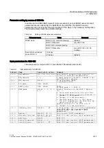
Страница 88: ... SIMATIC Manager by calling Setup exe in the directory daten S7_OM on the RFID Systems Software Documentation CD Currently the ASM 473 cannot be integrated in masters of other manufacturers Reader connection system A write read device always occupies the two M12 connection sockets X3 and X4 on the ASM 473 A prefabricated cable makes it easy to connect the write read device The standard model of th...

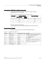
Страница 89: ...ion_1 B 16 00 02 04 See Section INPUT parameters 13 0 distance_limiting B 16 05 0A 0F 14 19 1E 23 MOBY U1 D1 see Section INPUT parameters 14 0 multitag B 16 1 MOBY U1 D1 or RF3001 15 0 field_ON_control B 16 0 1 2 MOBY U1 D1 see Section INPUT parameters 16 0 field_ON_time B 16 00 FF MOBY U1 D1 see Section INPUT parameters 1 valid only for 6GT2 002 0HA10 Table of commands for ASM 473 The assignment ...

Страница 90: ...n is available on ASM 473 with MLFB 6GT2 002 0HA10 Interfaces and indicators of the ASM 473 Figure A 3 Interfaces and indicators of the ASM 473 Table A 5 Pin assignment of sockets X3 X4 Socket Pin Pin Assignment write read device 1 RxD 2 TxD 3 TxD 4 RxD X3 5 PE 1 24 V 2 n c 3 0 V 4 n c X4 5 PE LEDs for PROFIBUS DP General indicators SF BF ON DC24V are located on the basic model of the ET 200X ...

Страница 91: ...ing ASM states are also indicated with the LEDs PRE and ERR PRE ERR Description Causes Remedy OFF ON ON perm Hardware is defective RAM flash ON OFF Loader is defective can only be fixed at the plant 2 Hz OFF Firmware loading process is active and or no firmware detected load firmware do not switch off ASM during this process 2 Hz 2 Hz Loading of firmware aborted due to error restart needed reload ...

Страница 92: ...is processed first This may significantly increase the processing time of the other write read device This is the reason dynamic processing of several MDSs simultaneously has not been approved 60BFKDQQHO 352 86 3 PDVWHU PRGXOH H J 6 38 352 86 OLQH 9 IRU 60 DQG ZULWH UHDG GHYLFH WR RWKHU 352 86 EXV QRGHV QG ZULWH UHDG GHYLFH ವ 1RW ZLWK 02 GLDORJ ವ 1RW ZLWK 02 8 5 b 7 FRPS 3 Figure A 4 ASM 452 confi...

Страница 93: ...M_address 256 260 264 268 Each ASM 452 occupies four bytes of I O in the I O area of the controller 2 0 ASM_channel 1 2 2 quasi parallel channels channel 2 not for MOBY U D I dialog 8 0 MDS_control B 16 0 1 0 no presence check 1 presence check 9 0 ECC_mode TRUE FALSE 9 1 RESET_long TRUE FALSE TRUE if MOBY_mode 5 MOBY U 10 0 MOBY_mode B 16 1 4 5 8 9 A B Special features of the MOBY I dialog 8 Write...

Страница 94: ...lize MDS all 04 44 SLG status U1 D1 08 48 Turn off MDS U 0A 4A Turn antenna on off With MOBY F the command is only effective when one write read device is used on the ASM 452 F U D 0B 4B MDS status U 1 Please read Section Command parameters 2 Chained commands are not supported by all write read devices please adhere to the information in the MOBY manuals for configuration mounting and service Sett...

Страница 95: ...n there is logic voltage at the ASM is generated by the 24 V supply voltage DC 24 V Lights up when the 24 V supply voltage is connected to the ASM LEDs for write read device Meaning SLG 1 Write read device 1 is selected SLG 2 Write read device 2 is selected Only write read device 1 or write read device 2 can be selected PRE ERR 1 Channel 1 MDS present or error display PRE ERR 2 Channel 2 MDS prese...

Страница 96: ...or PROFIBUS Pin Assignment X 11 and X 12 1 2 3 4 5 6 Signal B red PE PE not wired Signal A green L not wired M not wired Connection for power supply Pin Assignment X 13 1 2 3 4 5 6 PE L M PE L M Connection for write read device Pin Assignment X1 X3 1 2 3 4 5 RxD TxD TxD RxD PE X2 X4 Pin X2 X4 1 2 3 4 5 24 V PRE ERR2 0 V PRE ERR1 PE 24 V res DE1 0 V res DE0 PE ...

Страница 97: ...NPUT parameters Table A 9 Control of the LEDs PRE ERR1 and PRE ERR2 option_1 Meaning of PRE ERRx The LED indicates both ANZ_MDS_present and error_MOBY When an MDS is in the field ANZ_MDS_present 1 errors are not indicated by the LEDs The LED only indicates error_MOBY The LED only indicates ANZ_MDS_present The LED indicates both ANZ_MDS_present and error_MOBY When an error output is queued no ANZ_M...

Страница 98: ...ection to DP Master failed ASM 452 not detecting a baud rate Check the PROFIBUS DP connection Check the DP master On Status not relevant Bus interrupt DP Master not functioning Check all cables on your PROFIBUS DP network Check whether the connector plugs for PROFIBUS DP are securely plugged into the ASM 452 Flashe s On The configuration data sent to the ASM 452 by the DP master do not match the c...

Страница 99: ... UHDG GHYLFH ULWH UHDG GHYLFH ULWH UHDG GHYLFH 0 6 0 6 0 6 0 6 352 86 3 9 9 9 60BFKDQQHO 352 86 PDVWHU a Figure A 5 Configurator for ASM 454 Hardware configuration The ASM 454 is integrated into the hardware configuration of the SIMATIC Manager or into another PROFIBUS Master by means of the GSD file SIEM809F GSD The file is incorporated in the hardware configuration of the SIMATIC Manager using t...

Страница 100: ...te read device 4x 11 0 scanning_time B 16 00 FF A value other than 00 is only recommended when MOBY_mode was parameterized appropriately see Section INPUT parameters 12 0 option_1 B 16 00 02 04 See Section INPUT parameters 13 0 distance_limiting B 16 0 14 0 multitag B 16 1 15 0 field_ON_control B 16 0 16 0 field_ON_time B 16 0 Not relevant no MOBY U Table of commands for ASM 454 The assignment is ...

Страница 101: ...ED 5 35 55 QWHUIDFHV Interfaces 1 4 Connections for up to four write read devices ASM 454 PROFIBUS side LED Meaning ON green 24 V on ASM ACT green This LED flashes once briefly when a command is finished SF BF red System Fault Bus Fault RAM Error Interfaces Meaning PROFIBUS PROFIBUS DP interface SERIAL RS 232 RS 422 interface only relevant for firmware download 6HW 352 86 DGGUHVV 21 21 21 DPSOH 35...

Страница 102: ...gthen the processing times of the other channels SLAs This is the reason dynamic processing of several MDSs simultaneously has not been approved 02 SRZHU SDFN RU RWKHU 9 FRQQHFWLRQ 02 6 DQG 0 6 6 6 2WKHU PDVWHU WKLUG SDUW 352 86 PDVWHU 6 6 6 6 0 6 0 6 0 6 0 6 9 9 60BFKDQQHO a 352 86 3 9 Figure A 6 Configurator for ASM 754 Hardware configuration The ASM 754 is integrated into the hardware configura...

Страница 103: ...s may increase these times Input parameters for ASM 754 The assignment is made in UDT 10 see Section Parameter data block Table A 14 Input parameters for ASM 754 Address Name Permissible values Comment 0 0 ASM_address 256 264 272 280 Each ASM 754 occupies 8 byte of I O in the I O area of the control unit 2 0 ASM_channel 1 2 3 4 4 pseudo parallel channels 8 0 MDS_control B 16 0 1 0 no presence chec...

Страница 104: ...de in UDT 20 using the Command variable see Section Command parameter settings Table A 15 Commands for ASM 754 Command code normal Chained Description 01 41 Write to MDS 02 42 Read MDS read fixed code 03 43 Initialize MDS Switch settings interfaces and indicators of the ASM 754 See Section Switch settings interfaces and indicators of the ASM 454 in Chapter ASM 454 ...

Страница 105: ...r process image mode 352 86 PDVWHU a 6 6 6 6 0 6 0 6 0 6 0 6 9 9 60BFKDQQHO 352 86 3 9 02 SRZHU SDFN RU RWKHU 9 FRQQHFWLRQ 02 6 DQG 0 6 6 6 2WKHU PDVWHU WKLUG SDUW Figure A 7 Configurator for ASM 854 Hardware configuration The ASM 854 is integrated into the hardware configuration of the SIMATIC Manager or into another PROFIBUS Master by means of the GSD file SIEM809F GSD The file is incorporated i...

Страница 106: ...imiting B 16 0 14 0 multitag B 16 1 15 0 field_ON_control B 16 0 16 0 field_ON_time B 16 0 Not relevant no MOBY U Table of commands for ASM 854 The assignment is made in UDT 20 using the Command variable see Section Command parameter settings Table A 17 Commands of the ASM 854 when MOBY_mode B Command code normal Chained Description 01 41 Write to MDS 02 42 Read MDS 03 43 Initialize MDS 0A 4A Ante...

Страница 107: ...lecting process image mode for ASM 854 850 based on the number of channels Process image mode Operating principle After the ASM and PROFIBUS have powered up code 00 00 00 00 00 is stored in the process image for each MDS Each SLA channel immediately starts to scan its surroundings for a new MDS no As soon as the MDS no has been read the process image indicates the fixed code information The new MD...

Страница 108: ... over 3 ASM 854s CALL DPRD_DAT LADDR W 16 0 RET_VAL MW0 RECORD P DB20 DBX 0 0 BYTE 24 SFC14 1st ASM 854 has I O address 0 The data are stored in DB 20 starting at address 0 Since 4 channels are used the data length is 24 bytes CALL DPRD_DAT LADDR W 16 24 RET_VAL MW1 RECORD P DB20 DBX 24 0 BYTE 24 2nd ASM 854 has I O address 24 The data are stored in DB 20 starting at address 24 Since 4 channels ar...

Страница 109: ...LVWRULFDO UHDG LQIR ELW VHW ELW LQGLFDWHV WKDW WKH 0 6 PRYHG DFURVV WKH ILHOG DW PD LPXP SRVVLEOH VSHHG 7KH GDWD FRXOG RQO EH UHDG RQFH IURP WKH 0 6 QIRUPDWLRQ RQ FKDQQHO DOORFDWLRQ RI WKH GDWD KDQQHO KDQQHO KDQQHO UURU PHVVDJH LI HUURU 7KH GDWD DUH LQYDOLG DWD E WH FRQWDLQV DQ HUURU FRGH 7KH IROORZLQJ HUURU FRGHV DUH SRVVLEOH KH WKH 0 6 GDWD KDYH FKDQJHG ZLWKRXW D SUHVHQFH FKDQJH KH 60 SRZHU XS W...

Страница 110: ...elease 03 2006 J31069 D0167 U001 A2 7618 Process image mode time diagram UURU 6WDUW XS RI 60 1RUPDO UHDGLQJ RI QHZ 0 6 7KH VDPH 0 6 HQWHUV WKH UHDG ILHOG VHYHUDO WLPHV 1R FKDQJH RQ VW 0 6 QG 0 6 UG 0 6 WK 0 6 WK 0 6 UURU 35 DWD Figure A 10 Time diagram for process image mode ...

Страница 111: ...ection ASM 854 352 86 PDVWHU 6 0 6 9 9 60BFKDQQHO a 352 86 3 9 02 SRZHU SDFN RU RWKHU 9 FRQQHFWLRQ 02 6 DQG 0 6 6 6 2WKHU PDVWHU WKLUG SDUW Figure A 11 Configurator for ASM 850 Hardware configuration The ASM 850 is integrated into the hardware configuration of the SIMATIC Manager or into another PROFIBUS Master by means of the GSD file SIEM809F GSD The file is incorporated in the hardware configur...

Страница 112: ...me B 16 00 No parameterization of the scanning time 12 0 option_1 B 16 00 01 04 08 See Section INPUT parameters 13 0 distance_limiting B 16 0 14 0 multitag B 16 1 15 0 field_ON_control B 16 0 16 0 field_ON_time B 16 0 Not relevant no MOBY U Table of commands for ASM 850 The assignment is made in UDT 20 using the Command variable see Section Command parameter settings Table A 18 Commands of the ASM...

Страница 113: ...o be considered by SIMATIC users It is intended particularly for programmers of PCs and third party PLCs The information enables the programmer to develop customized function blocks or drivers for the MOBY ASM Note Some signals in this appendix have the same meaning as the variables in Section Parameter data block In order to distinguish between them an underscore _ is appended to the relevant sig...

Страница 114: ...LD 352 86 3 6WDWXV LQIRUPDWLRQ LV H FKDQJHG VHH 6HFWLRQ FOLF FRQWURO ZRUG EHWZHHQ PDVWHU DQG 02 60 2WKHU ILHOG GHYLFHV 352 86 3 9 02 60 02 60 The master may only send new commands to the slave MOBY ASM when the ASM is ready Status information is used to indicate that the MOBY ASM is ready The same applies to acknowledgments The MOBY ASM may only fetch new acknowledgments when a new acknowledgment ...

Страница 115: ...efined state to the next A new DP V1 telegram is not permitted until the next state is reached A DP V1 telegram is either a command to the ASM or an acknowledgment from the ASM For this reason it is important to tell the master whether a new DP V1 telegram can be executed Each state is coded in 2 bits and counted up as shown in the diagram above hence the name state bits or state counters The stat...

Страница 116: ... acknowledgement state with higher priority I e when the user wants to send a telegram to the ASM but a telegram from the ASM is waiting to be fetched at the same time the telegram from the ASM must be fetched first Both the command and the acknowledgment state are coded in 2 bits each Both states are stored in a byte see Section Cyclic control word between master and MOBY ASM ...

Страница 117: ...IRUFHV D 02 60 VWDUW XS LW LV VXEVHTXHQWO VHW LQ WKH SHULSKHUDO LQSXW FNQRZOHGJHPHQW FRXQWHU KLJKHU ELW 4 FNQRZOHGJHPHQW FRXQWHU ORZHU ELW 4 5HVHUYHG 3HULSKHUDO LQSXW 5HVHUYHG IRU 2 5HDGHUBHUURU 02 8 RQO UHSHDWBFRPPDQGB RSWLRQDO 1 BFDQFHOB DQFHO DFNQRZOHGJH PHQW 0 6BSUHVHQFHB FKDQJHGB IRU XQXVHG QXPEHUB0 6B 02 8 RQO FDQFHOB FRPPDQG WHUPLQDWLRQ 1 B0 6B SUHVHQWB SUHVHQFH FRPPDQGBUHSHDWBDFWLYHB 7KLV ...

Страница 118: ... and acknowledgment QZ counters are synchronized during a start up The ASM sets QZ 0 and BZ 1 The start up can be triggered by both the ASM return of power and the user init_run_ 5 6 7 FRPPDQG WR 60 5 6 7 FRPPDQG IURP 60 F FOLF WHOHJUDP 4 DQ YDOXH I D FRPPDQG ZDV LQWHUUXSWHG E D 5 6 7 RU LQLWBUXQB HUURU PHVVDJH LV WULJJHUHG KHUH UHDG UHDG PHVVDJH LQ XVHU SURJUDP UHDG 4 GHILQHG UHVHW 4 LQLWBUXQB 1 ...

Страница 119: ...eset with Cancel FNQRZOHGJHPHQW ZLWK HUURU F FOLF WHOHJUDP DQFHO LI QR FRPPDQG DFWLYDWHG DQFHO LI 60 FXUUHQWO SURFHVVLQJ D FRPPDQG RQO RQH HUURU DFNQRZOHGJHPHQW LV PDGH LI VHYHUDO FRPPDQGV FRPPDQG FKDLQV DUH FDQFHOHG WKH LQFUHPHQWDWLRQ RI 4 DQG ZLWKGUDZDO RI Q BFDQFHOB FDQ EH LQGLFDWHG VLPXOWDQHRXVO WR WKH XVHU UHDG UHDG PHVVDJH LQ XVHU SURJUDP UHDG FDQFHOB 1 BFDQFHOB 4 4 ณณ ณณ ณณ ณณ Figure B 5 Ca...

Страница 120: ...tive commands The following diagram shows the sequence of command and acknowledgement exchange between user DP master and MOBY ASM 3 PDVWHU 02 60 7KH FRPPDQG DQG DFNQRZOHGJHPHQW WHOHJUDP LV DQ DF FOLF 3 9 WHOHJUDP ZLWK 3 9 UHVSRQVH VWDUW LV RQO DOORZHG DIWHU FKDQJLQJ WKH FRPPDQG DQG RU DFNQRZOHGJHPHQW FRXQWHU KDQJH FRPPDQG FRXQWHU 1HZ VWDWXV ROG VWDWXV F FOLF ZRUG KDQJH DFNQRZOHGJHPHQW FRXQWHU 1HZ...

Страница 121: ...HOHJUDP LV DQ DF FOLF 3 9 WHOHJUDP ZLWK 3 9 UHVSRQVH VWDUW LV RQO DOORZHG DIWHU FKDQJLQJ WKH FRPPDQG DQG RU DFNQRZOHGJHPHQW FRXQWHU KDQJH FRPPDQG FRXQWHU 1HZ VWDWXV ROG VWDWXV F FOLF ZRUG KDQJH DFNQRZOHGJHPHQW FRXQWHU 1HZ VWDWXV ROG VWDWXV F FOLF ZRUG 1R FKDQJH WR F FOLF GDWD 7LPH D LV VW FRPPDQG QG FRPPDQG UG FRPPDQG HFXWLRQ RI VW FRPPDQG LQ 60 HFXWLRQ RI QG FRPPDQG LQ 60 HFXWLRQ RI UG FRPPDQG LQ...

Страница 122: ...art of the same PROFIBUS branch The cycle time of PROFIBUS becomes irregular and sporadically may become very high When more commands are to be processed by the ASM than ASM buffer space the user must first fetch results from the ASM before new commands can be sent to the ASM The ASM does not absolutely require the chaining bit in the command However from the user s point of view it is an elegant ...

Страница 123: ...UHVHQWB WKH FRPPDQG LV VWDUWHG LPPHGLDWHO 60BEXV B LPPHGLDWHO LQGLFDWHV WKH SURJUDPPLQJ RI D FRPPDQG 7KH FRPPDQG LV H HFXWHG WKH DFNQRZOHGJHPHQW FRXQWHU LV GHFUHPHQWHG DQG WKH UHVXOW LV WUDQVIHUUHG DVW 0 6 VHTXHQFH H HFXWLRQ RI WKH QHZ 0 6 LV IDVWHU WKDQ WKH WUDQVPLVVLRQ RI WKH GDWD 7KH FRPPDQG DQG DFNQRZOHGJHPHQW WHOHJUDP LV DQ DF FOLF 3 9 WHOHJUDP ZLWK 3 9 UHVSRQVH VWDUW LV RQO DOORZHG DIWHU FKD...

Страница 124: ...W FRXQWHU LV LQFUHPHQWHG DQG WKH UHVXOW LV WUDQVIHUUHG 7ULJJHU VLJQDO IRU D FRPPDQG VWDUW 1 B0 6BSUHVHQWB ൺ 8VHU VWDUWV ZLWK UHSHDWBFRPPDQGB DQGVKDNH VHTXHQFH WR PDNH VXUH FRPPDQG LV SURFHVVHG SSOLFDWLRQ ZDLWV KHUH IRU QH W 0 6 3URFHVVLQJ VHTXHQFH IRU DQRWKHU 0 6 RPPXQLFDWLRQ GLUHFWLRQ 7KH FRPPDQG DQG DFNQRZOHGJHPHQW WHOHJUDP LV DQ DF FOLF 3 9 WHOHJUDP ZLWK 3 9 UHVSRQVH VWDUW LV RQO DOORZHG DIWHU ...

Страница 125: ...ZLQJ PHDQLQJ IRU D UHVXOW RU HUURU WHOHJUDP 7KH LPSOHPHQWHG FRPPDQGV DUH GHVFULEHG RQ WKH IROORZLQJ SDJHV HQHUDO FRPPDQG IRUPDW PRXQW RI E WHVQ WRWDO QXPEHU RI E WHV LQ WHOHJUDP E WH LV QRW FRXQWHG PLQLPXP PD LPXP PD LPXP OHQJWK IRU 352 86 3 9 LV E WHV DWW DWW UURU FRGH LW FRUUHFWLRQ ZDV SHUIRUPHG WKH GDWD LQ WKH UHVXOW WHOHJUDP DUH 2 DWWHU YROWDJH RQ 0 6 KDV GURSSHG EHORZ WKUHVKROG 7KLV ELW LV DO...

Страница 126: ...OBY I MOBY I MOBY I MOBY E MOBY F MOBY F MOBY U MOBY U MOBY D MOBY D MOBY D MOBY D RF300 RF300 RF300 RF300 0 1 s 0 4 s 0 8 s 18 s 3 s 0 8 s 2 2 s 0 25 s approx 1 s approx 1 5 s approx 0 2 s 0 3 s 1 2 s 2 4 s 5 s 20 s 54 s 75 s 00 05 00 00 08 00 00 20 00 00 20 00 00 80 00 00 02 F0 00 00 C0 00 00 10 00 08 00 00 80 00 00 00 2C 00 00 70 00 01 00 00 04 00 00 00 14 00 20 00 00 80 00 00 FF 00 4 44 SLG st...

Страница 127: ...Release 03 2006 J31069 D0167 U001 A2 7618 B 15 Comma nd code hex Comman d code chained hex Command Description A 4A Antenna on off Only MOBY F U D or RF300 This command turns the antenna field on the write read device off and on again B 4B MDS status Returns the characteristics of the MDS in the result ...

Страница 128: ...0 6 W6 1 60 SRZHU XS LV RQO VLJQDOHG WR WKH XVHU YLD WKH F FOLF ZRUG VHH SSHQGL LW 7LPHRXW 60 UHVSRQGV ZLWK HUURU LI QR 0 6 SUHVHQW 237 5HVXOW WHOHJUDP IURP 02 60 RPPDQG WHOHJUDP WR 02 60 RPPDQG FRGH 6WDUWXS LUPZDUH YHUVLRQ LQ 60 YHUVLRQB02 B H J KH KH 9 5HV 9HUV 9HUV 5HVHW 55 VWRS IODVKLQJ 3UHVHQFH FKHFN DQG 0 6 FRQWURO 0 6BFRQWUROB QR SUHVHQFH FKHFN QR 0 6 FRQWURO SUHVHQFH FKHFN YLD ILUPZDUH GHI...

Страница 129: ...FDEOH FRQQHFWLRQ DFWLYDWHG VHH PDQXDO IRU FRQILJXULQJ PRXQWLQJ DQG VHUYLFH IRU 02 8 02 b8 GLVWDQFHBOLPLWLQJB VHH LQSXW SDUDPHWHUV KH P KH GLWWR ZLWK UHGXFHG VHQG SHUIRUPDQFH 5 XQXVHG KH 02 b8 02 UDWLQJ VHH LQSXW SDUDPHWHUV ILHOGB21BWLPHB VHH LQSXW SDUDPHWHUV KH ZLWKRXW 52V KH KH V 21 GXUDWLRQ IRU WKH ZULWH UHDG GHYLFH ILHOG 02 b8 02 0 6 W SH VHH LQSXW SDUDPHWHUV KH FRGH H J 0 6 KH 62 0 6 5 XQXVHG ...

Страница 130: ...WKH GDWD WR EH SURFHVVHG RQ WKH 0 6 06 0RVW VLJQLILFDQW DGGUHVV SRUWLRQ 6 HDVW VLJQLILFDQW DGGUHVV SRUWLRQ 1XPEHU RI FKDUDFWHUV LQ WKH WHOHJUDP 1 5HPDUNV PD QRW EH JUHDWHU WKDQ WKH EXV FRQILJXUDWLRQ 1 7 SDWWHUQ XULQJ LQLWLDOL DWLRQ WKH 0 6 LV ZULWWHQ ZLWK WKH YDOXH 1 7 SDWWHUQ QG DGG 0HPRU VL H RI WKH 0 6 Q WKH HYHQW RI DQ HUURU WKH IRUPDW RI WKH UHVXOW WHOHJUDP LV DV IROORZV 7KH E WH FDQ VWRUH D ...

Страница 131: ...9 RPPXQLFDWLRQ TXDOLW PRGH ZULWH UHDG GHYLFH GLDJQRVWLFV PRGH ULWH UHDG GHYLFH GLDJQRVWLFV LGHQWLILHG 0 6 PRGH ULWH UHDG GHYLFH GLDJQRVWLFV HUURU PHVVDJHV PRGH ULWH UHDG GHYLFH GLDJQRVWLFV XQFWLRQ FDOOV PRGH ULWH UHDG GHYLFH VWDWXV 7KH PHDQLQJ RI WKH ZULWH UHDG GHYLFH VWDWXV LV GHVFULEHG LQ 8 7 VW FRPPDQG 7HOHJUDP KHDGHUV RI ODVW FRPPDQGV H HFXWHG QWK FRPPDQG VW HUURU QGLFDWHV ODVW HUURU ZKLFK RFF...

Страница 132: ...069 D0167 U001 A2 7618 1 7 1 PRGH 6WDW RPPDQG FRGH RPPDQG WHOHJUDP WR 02 60 5HVXOW WHOHJUDP IURP 02 60 3URFHVVLQJ ZLWK WKLV 0 6 KDV WHUPLQDWHG 3URFHVVLQJ SDXVH ZLWK WKH 0 6 7HUPLQDWH VFDQQLQJBWLPH IRU 02 8 0 6 LPPHGLDWHO PRGH 6ZLWFK RQ DQWHQQD 6WDQGE VZLWFK RII DQWHQQD 0DWFK DQWHQQD WR HQYLURQPHQW 02 7 DQWHQQD 21 2 6WDW 6WDW ...

Страница 133: ...7DJ 7 SH 6WDW LJKW E WH WDJ QXPEHU XQLTXH LGHQWLILHU RPPDQG FRGH RPPDQG WHOHJUDP WR 02 60 5HVXOW WHOHJUDP IURP 02 60 ZHHN FDOHQGDU ZHHN KH KH XS WR ZHHN HDU HDU XUUHQW GDWH ZHHN HDU QR PHDQLQJ ZHHN HDU QR PHDQLQJ RXU E WH WDJ QXPEHU 7KH PHDQLQJ RI WKH GLDJQRVWLF GDWD LV GHVFULEHG LQ 8 7 7KH PHDQLQJ RI WKH GLDJQRVWLF GDWD LV GHVFULEHG LQ 8 7 7KH PHDQLQJ RI WKH GLDJQRVWLF GDWD LV GHVFULEHG LQ 8 7 0 ...

Страница 134: ... PEW are exchanged cyclically between ASM and function block PEW tells the function block when commands and data may be transferred to the ASM Commands and data are put into data records 60BDGGUHVV 60BFKDQQHO 0 6BFRQWURO BPRGH 02 BPRGH VFDQQLQJBWLPH 60b 02 60 3 3 3 3 6 3 1 6 3 1 6 3 6 3 6 Q 6 6 6 6 SDUDPHWHUV 6 GDWD RPPDQGV DWD DFNQRZO HGJHPHQWV XQFWLRQ EORFN QWHUIDFH WR XVHU 0 6 GDWD 02 GULYHU 6H...

Страница 135: ...he layout of a non cyclic data record SAP 51 is used to transmit the data The data unit DU indicates how the MOBY ASM is addressed 6 U 6 6 6 3 66 3 8 6 XQFWLRQ FRGH H J 6B5HDG UHT QGH ฬ GDWD UHFRUG QXPEHU IRU FKDQQHOV WR VHH WDEOH EHORZ DWD OHQJWK 6ORWB1XPEHU 60 60 WR WR FRUUHVSRQGV WR WKH VORW ZLWKLQ DQ 7 0 7 5HTXHVW 5HVSRQVH RND 5HVSRQVH UURU UDPH WH WH WH WH ...

Страница 136: ... 150 151 231 232 233 234 239 246 248 255 ASM 475 473 ASM 475 473 RF170C RF170C RF170C RF170C ASM 475 473 456 RF170C ASM 475 473 456 ASM 475 473 456 RF170C ASM 456 Reserved diagnosis of powerparameters Reserved diagnostic buffer I M0 module data I M1 maintenance data 1 I M2 maintenance data 2 I M3 maintenance data 3 FW update optional Reserved read FW version Reserved SZL list Reserved I M function...

Страница 137: ... 80 00 80 00 00 16 68 0b 0b 68 02 03 08 88 00 88 00 88 00 88 00 00 16 ASM sets the command counter to one 68 0b 0b 68 03 02 7d 00 00 00 00 00 00 00 00 00 16 68 0b 0b 68 02 03 08 88 00 88 00 88 00 88 00 00 16 FC resets the start up bit 68 0b 0b 68 03 02 5d 00 00 00 00 00 00 00 00 00 16 68 0b 0b 68 02 03 08 08 00 08 00 08 00 08 00 00 16 ASM also resets the start up bit 68 0f 0f 68 83 82 5c 33 36 5f ...

Страница 138: ...36 5e 01 65 06 00 16 Request for an acknowledgment from ASM 68 05 05 68 83 82 5c 33 36 00 16 68 0f 0f 68 82 83 08 36 33 5e 01 65 06 05 00 00 00 00 00 00 16 RESET acknowledgment 68 0f 0f 68 83 82 7c 33 36 5f 01 6f 06 05 02 00 00 40 0c 00 16 Read command MDS addr 0 length 0c 68 05 05 68 83 82 7c 33 36 00 16 68 09 09 68 82 83 08 36 33 5f 01 6f 06 00 16 Acknowledgment that read is in progress 68 09 09...

Страница 139: ...tion support request You can find the latest general information about our RFID systems on the Internet at http www siemens com simatic sensors rfid You can find the catalog and online ordering systems at http www siemens com automation mall C 2 C 2 Contacts If you have any further questions on the use of the products described in this manual please contact one of our representatives at your local...

Страница 140: ...06 J31069 D0167 U001 A2 7618 C 3 C 3 Training Training center We offer appropriate courses to get you started Please contact your regional training center or the central training center in D 90327 Nuremberg Germany Telephone 49 911 895 3200 http www siemens com sitrain ...

Отзывы: