4
Installation and Testing
NOTE
Several proprietary test sets are marketed which
combine the current source and timer, and include
other features to simplify setup.
4. 7.2
Preliminary Steps
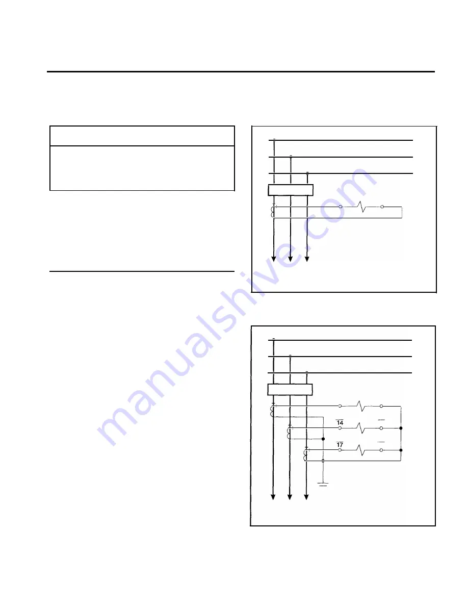
1 . With the connecting plugs removed, connect the unit as
shown in the following figure numbers:
1 st Digit of
Figure
Style Number Sensing Input Configuration
Number
K
Single-phase
8
G
Three-phase
9
H
Three-phase-with-ground
1 0, 1 1
X
Two-phase-with -ground
1 2
2. Insert the relay connecting plugs if bench testing. If relay is
installed, insert test plugs instead . Before applying power,
check that the Relay Fail contact is closed (terminals 1 1 and
1 2).
3. Apply operating power at terminals 3 and 4. Verify that the
POWER LED is lit, and that the relay disabled contact is
open.
4. Load 00 into the Phase Tap Cal register.
5. Load 99 into the Time Dial register.
4.7.3
Time Overcurrent Pickup Test
The phase current pickup of the relay will be set at the factory
to operate on one of the two available ranges: HIGH or LOW. If
ground current is monitored, it will also be set for one of the two
ranges. Determine which range applies by noting the indication
of the tap range on the front panel. (One for phase and one for
ground.)
BUS
52
A
B
C
LINE
Page 2 1
A
B
c
51
51
8
A
7
LEGEND
51
52
OVERCURRENT RELAY
POWER CIRCUIT BREAKER
Figure 8.
Single-Phase Current Sensing Connections
BUS
52
A
B
C
LINE
51
A
51
8
7
51
B
51
1 5
5 1
c
51
1 8
-
LEGEND
51
OVERCURRENT RElAY
A
B
c
52
POWER CIRCUIT BREAKER
Figure 9.
Three-Phase Current Sensing Connections
www
. ElectricalPartManuals
. com


