


2
Controls and Indicators
2.1
General
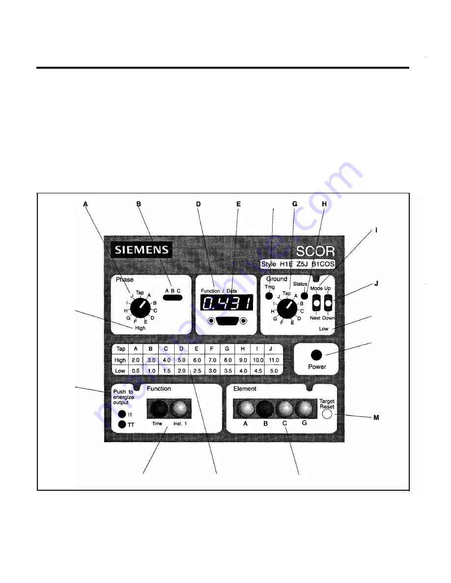
Figure 3
shows the front panel of the SCOR relay with all the
options installed except Option
1-2.
All of the front panel
controls and indicators are called out and assigned a locator
letter.
Table 2
supplies a description for each. Data is displayed
c
Q
p
0
Page
6
in primary kilo amperes. The Time Target and Element
B
Target
are shaded darker, indicatingthatthe relay caused an overcurrent
timed trip due to a fault on Phase
B,
and the targets have not
been reset.
F
K
L
N
Figure 3.
Controls and Indicators
www
. ElectricalPartManuals
. com


