1
General Information
Page 4
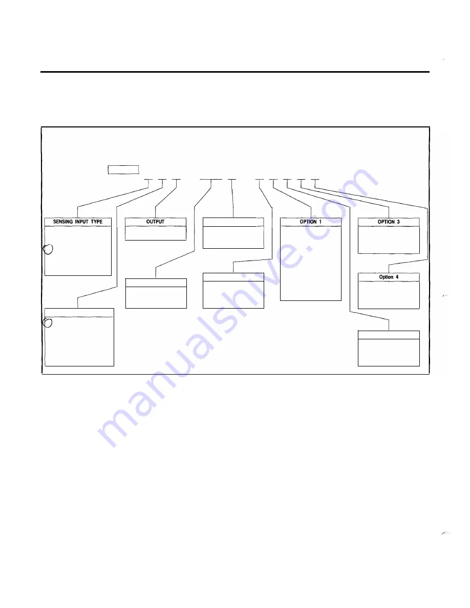
Style Number Identification Chart for Siemens SCOR Relay
SCOR
D D [§]
-
� [i] D - � D D D �
Power Supply
E
=
N.O. Contacts
K
=
48
Vdc
0
=
None
0
=
None
K
=
Single-Phase Current
®
G
=
Three-Phase Current
®
H
=
Three-Phase-with-
J
=
125 Vdc/120 Vac
1
=
One lnst. Element
CD
2
=
Two lnst. Elements
CD
1
=
Power Supply
Hold-up Circuit
Ground Current
X
=
Two-Phase-with
Ground Current
TIMING
TARGET
OR
One Ins!. Element
and one External-
®
Program-Controlled
Contact
Z5
=
Switch Selectable
8
and C Timing
Curves
B
=
Function targets are
current operated;
element tergets are
internally operated.
OR
Separate
Ground Trip
Contact
S
=
Semi-Flush
Mounting
SENSING INPUT TAP RANGE
NOTES:
1
=
2.0 - 11 A for all phases
0.5 - 5.0 A for ground
2
=
0.5 - 5.0 A for all phases
2.0 - 11 A for ground
CD
Each element includes a relay which energizes for either a
phase or a ground instantaneous trip.
Option 2
N
=
None
3
=
0.5 - 5.0 A for all inputs
4
=
2.0 - 11 A for all inputs
®
Sensing input range must be 3 or
4.
C
=
Communications
Board Installed
@
Option 2 must be C.
Figure 2
Style Number Identification Chart
MIN/MAX log,
which contains the minimum and maximum
current and demand values which have occurred since last
cleared.
Configuration data
for all registers listed in
Table 3 (Page
1 1
),
including time overcurrent function and curve selected,
pickup settings, and current transformer ratios.
Whichever port is used, all communications must be initiated by
the Power Monitor unit or computer. When addressed, all of the
relay's storage registers may be read by the Power Monitor unit,
and many of them can be altered. (Password protected .)
1.10 Breaker Failure
When the relay includes the Communications Option, a "Breaker
Failuare" feature is provided. This functions to signal if the circuit
breaker does not open immediately after operation of a time
and/or instantaneous output relay.
The breaker failure function involves a 1 -second timer. When a
trip occurs, the timer starts. At time-out, two checks are made;
one, that the breaker properly changed state (opened), and two,
that the current is below approximately 1 0% of the tap value. If
the result of either check is not correct, then it is assumed that
the circuit breaker has failed to open and/or failed to interrupt the
current.
If a breaker failure is detected, a time-stamped message
"Breaker Failure" is sent to the Power Monitor unit Event Log.
This feature may be disabled at Display Sequence 21 of the
Configuration Menu (see
Page 1 1).
1.11 Style Number (Figure 2)
The style number of the relay determines the features to be
included (or ordered) for a particular application. Each available
option is represented by a character as shown in
Figure 2
Style
Number Identification Chart.
www
. ElectricalPartManuals
. com


