External Accessories
63
Display Module and Ground Fault Monitor
The Ground Fault Monitor (GFM) is an optional module that
allows the user to locally monitor the ground fault current and
can be used in trip units with or without the integral ground
fault protection function . Trip units with the integral ground
fault protection function are identified by a “G” in the catalog
number and the presence of ground fault adjustments on the
face of the trip unit. If the trip unit is equipped with ground fault
protection, the Ground Fault Monitor utilizes the same ground
fault sensing method as the electronic trip unit. If the trip unit
is not equipped with ground fault protection, then the GFM
uses a residual ground fault sensing method. The Ground
Fault Monitor works independently from the trip unit’s ground
fault protection .
Ground Fault Monitor Settings
There are three ground fault pickup levels offered on the
Ground Fault Monitor:
“LO” equals 20 percent of the frame rating.
“HI” equals either the frame rating or 1200 amps, which-
ever is less.
“MED” equals the average of the “LO” and “HI” pickup
levels.
The ground fault delays are divided into three fixed time delay
bands: 0.1, 0.3, and 0.5 seconds. The “MAX” setting is
defined as a 1200 amp pickup and 0.5 second delay.
Display
The Ground Fault Monitor displays the ground fault cur-rent in
amps. Then the ground fault current reaches a level 12
percent below the selected pickup setting, the amps display
will start to flash. Then the ground setting, the display will flash
“-OL-” for overload and the alarm line will be set to its’ “ON”
state.
Remote Interface
The Ground Fault Monitor can be utilized with a Display
Module Relay (mounted inside the breaker) or a Remote
Indicator Panel (externally mounted) to provide a set of relay
contacts for ground fault alarm. When used in conjunction
with either of these devices and a Shunt Trip, the Ground Fault
Monitor can be used as Ground Fault Sensing and Relaying
Equipment per U. L. 1053. For more information see the
Installation Instructions for the Ground Fault Sensing and
Relaying System.
Also, note that if the Ground Fault Monitor is removed while the
circuit breaker is powered up the alarm line will be set to its’
“ON” state
NOTE: Option for Ground Fault Detection and Alarm
without tripping in accordance with NEC Article 700
Section 700-26 is available. Consult Siemens Sales
Office for further information.
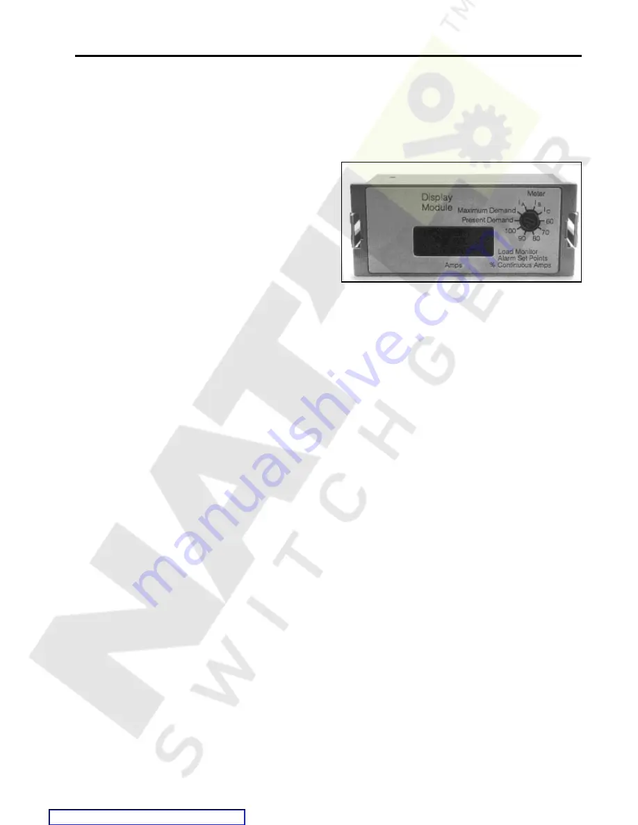
Ground Fault Monitor and Display Module
Display Module
The Display Module provides features for allowing the user to
locally monitor the phase currents. The switch to set and
select the display is accessible to the user through a hole in the
transparent cover of the trip unit.
Display Module
Maximum Current Demand
This feature provides a display of the maximum current
demand since the unit was last reset. The unit is reset by
depressing both the phase and ground fault test pushbuttons
simultaneously. Phase and ground fault pushbuttons are
located on the SB Electronic Trip Unit in the integral testing
section.
Present Current Demand
This feature provides a display of the present current de-
mands. The present current demands are calculated aver-
ages over thirty (30) minute intervals. The user may display the
most recent stored values by setting the switch to the present
demand position for the 30-minute interval.
Local Monitor Relay
This feature provides a local alarm display and an output signal
for an external alarm when the average of the phase currents
exceeds the alarm set point. The display automatically resets
itself when the alarm condition ceases. The output alarm
signal is a 5-volt DC level. The signal may be used to display
an alarm on a remote indication panel or by using an internal
Systems Breaker Modular Relay (SBDMR) . The alarm set
point may be set to 60, 70, 80, 90, or 100 percent of the
continuous current setting.
Load Current Meter
This feature provides a local display of the present 3-phase
currents. The user may display the current value by setting the
switch to the I
A
, I
B
, or I
C
positions.
Before installing the display module, the breaker should be
placed in the open position.
The display module is a plug-in unit. To install the module:
1. Remove the trip unit’s transparent cover.
2. Remove cover from the display module receptacle.
3. Insert the module into the receptacle.
4. Replace and seal the transparent cover.
Содержание SBA 1200
Страница 68: ...66 External Accessories Ground Fault Sensing and Relaying Courtesy of NationalSwitchgear com ...
Страница 88: ...86 Outline Dimension Drawing 2000A Stationary Drawout Element Courtesy of NationalSwitchgear com ...
Страница 89: ...87 Outline Dimension Drawing 2000A Stationary Drawout Element Courtesy of NationalSwitchgear com ...
Страница 90: ...88 Outline Dimension Drawing 2000A Moveable Drawout Element Courtesy of NationalSwitchgear com ...
Страница 91: ...89 Outline Dimension Drawing 2000A Moveable Drawout Element Courtesy of NationalSwitchgear com ...
Страница 92: ...90 Outline Dimension Drawing 800A Fixed Mounted 1200A Fixed Mounted Courtesy of NationalSwitchgear com ...
Страница 93: ...91 Outline Dimension Drawing 800A Fixed Mounted 1200A Fixed Mounted Courtesy of NationalSwitchgear com ...
Страница 94: ...92 Outline Dimension Drawing 2000A Fixed Mounted Courtesy of NationalSwitchgear com ...
Страница 95: ...93 Outline Dimension Drawing 2000A Fixed Mounted Courtesy of NationalSwitchgear com ...
Страница 100: ...98 Courtesy of NationalSwitchgear com ...
Страница 101: ...Electrical Diagrams 99 Courtesy of NationalSwitchgear com ...
Страница 102: ...100 Electrical Diagrams Courtesy of NationalSwitchgear com ...


