Internal Accessories
43
Electric Motor Operator
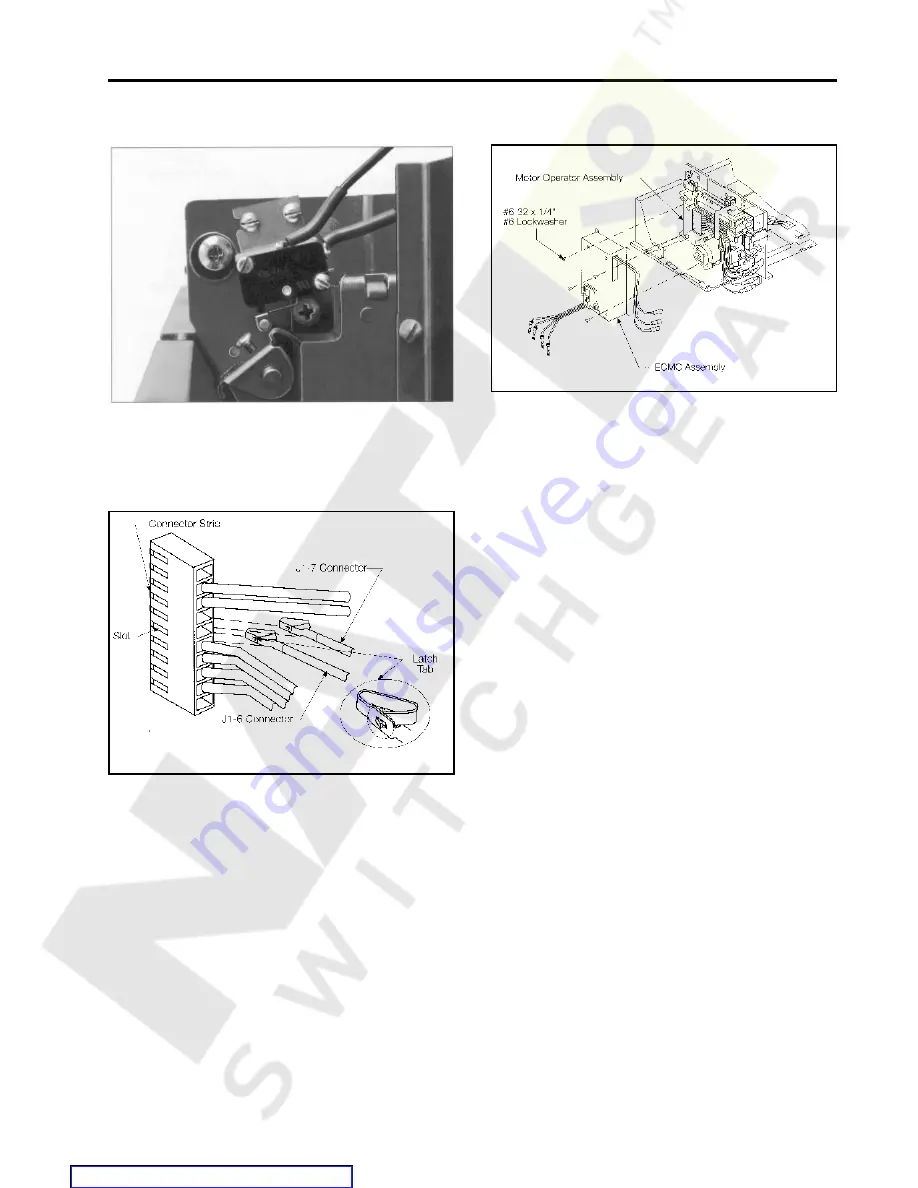
7.) Adjust the switch while holding the Actuator against the
switch body. Adjust the switch so that there is .11-12
inch clearance between the switch Actuator and the
Latch Lever. Tighten screws to 9-11 in. Ibs. Check
adjustment after tightening screws and read just if
necessary.
8.) Plug J1-6 and J1-7 Connectors into the Connector Strip
until latch tabs snap into slots Gently pull wires to ensure
they are latched into the Connector Strip.
9.) Install the Electric Motor Controller (ECMC Assembly) to
the Motor Operator Assembly with the four #6-32 x l/4"
screws and #6 lockwwashers. Torque screws to 9-11
in.-lbs.
Содержание SBA 1200
Страница 68: ...66 External Accessories Ground Fault Sensing and Relaying Courtesy of NationalSwitchgear com ...
Страница 88: ...86 Outline Dimension Drawing 2000A Stationary Drawout Element Courtesy of NationalSwitchgear com ...
Страница 89: ...87 Outline Dimension Drawing 2000A Stationary Drawout Element Courtesy of NationalSwitchgear com ...
Страница 90: ...88 Outline Dimension Drawing 2000A Moveable Drawout Element Courtesy of NationalSwitchgear com ...
Страница 91: ...89 Outline Dimension Drawing 2000A Moveable Drawout Element Courtesy of NationalSwitchgear com ...
Страница 92: ...90 Outline Dimension Drawing 800A Fixed Mounted 1200A Fixed Mounted Courtesy of NationalSwitchgear com ...
Страница 93: ...91 Outline Dimension Drawing 800A Fixed Mounted 1200A Fixed Mounted Courtesy of NationalSwitchgear com ...
Страница 94: ...92 Outline Dimension Drawing 2000A Fixed Mounted Courtesy of NationalSwitchgear com ...
Страница 95: ...93 Outline Dimension Drawing 2000A Fixed Mounted Courtesy of NationalSwitchgear com ...
Страница 100: ...98 Courtesy of NationalSwitchgear com ...
Страница 101: ...Electrical Diagrams 99 Courtesy of NationalSwitchgear com ...
Страница 102: ...100 Electrical Diagrams Courtesy of NationalSwitchgear com ...


