Operating Instructions
35
Trip Unit Test and Monitoring Functions
Siemens Electronic Trip Unit is equipped with three standard
test and monitoring functions to aid the user in the installation
and operation of the SB breaker.
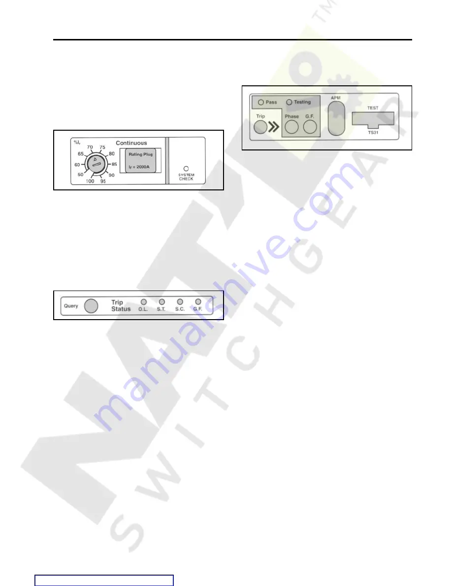
System Check Indicator
Integral Test Modes
Part Three - Monitoring the Electronic Trip Unit
The System Check Indicator is a green LED that blinks
approximately once every 3 seconds when the microproces-
sor is properly cycling through its protection routines.
The trip unit derives its operating power from the phase
currents in the SB breaker. The phase current required to
operate the trip unit is approximately 20 percent of the frame
rating (I
r
). If the microprocessor is not properly cycling through
its protection routines, the phase current is below 20% I
n
, the
LED will not light.
Trip Status
The trip Query button and Trip Status indicator lights provide
the user the means for determining what type of fault caused
the trip unit to trip the breaker. Fault indicators are provided
for:
O.L. - Overload or Long Time Fault
S.T. - Short Time Fault
S.C. - Short Circuit or Instantaneous Fault
G.F. - Ground Fault
When a fault occurs, the fault information is stored in the trip
unit by latching the appropriate red LED fault indicator to the
“On” position. When the Query button is depressed, the
latched fault indicator will light. The electrical power to the
indicators is automatically stored in the trip unit, eliminating
the need for a battery pack. A hole is provided in the
transparent cover to allow the user access to the Query
button.
NOTE: During trip unit power up, a fault indicator LED
will latch, providing a means to check that the circuitry
is properly operating. In the case of a fault, the proper
indicator will be latched to the fault position. The
indicator circuitry always latches the most recent
event.
The integral test function enables the user to “exercise the trip
unit electronics, the magnetic latch, and the breaker mecha-
nism. The purpose of the integral test function is to provide
the user an easy means to conduct a “go/no go” type test
before bringing the breaker on-line. After the breaker has
been brought on-line, it may be used during routine inspec-
tion and maintenance.
Both phase fault current protection and ground fault current
protection may be tested . The integral ground fault test
function tests the circuit breaker’s ground fault protection
system in accordance with NEC Article 230-95(c).
Electrical power to operate the integral test function is
provided internally, if the breaker is closed and the phase
currents are greater than 20% of the frame ampere rating In,
or by a plug-in power source (see Accessories section).
The user may execute the test function in either a “no trip”
mode, which will test only the trip unit electronics, or a “trip”
mode, which will also test the magnetic latch and breaker
mechanism. The execution of the integral test function in both
the “no trip” and “trip” modes is based on the settings of the
long time delay and ground fault delay adjustments. There-
fore, the Phase Test will take several seconds to execute and
the Ground Fault Test will appear to be nearly instantaneous.
To execute a test function in the “no trip” mode, depress the
appropriate pushbutton test switch,
Phase
or
GF
. As the trip
unit is performing the test, the
Testing
Indicator will light. If
the trip unit successfully passes the test, the
Pass
Indicator
will light. If the Pass Indicator does not light after the Testing
Indicator indicates that the test is complete, a more extensive
test should be run with Siemens TS-31 Universal Test Kit (see
Accessories).
CAUTION: Before conducting a “Trip” test on a SB
breaker which is “Closed” and in service, caution
should be taken to evaluate effects on downstream
loads. The breaker will open during testing, resulting in
a disruption of service.
Содержание SBA 1200
Страница 68: ...66 External Accessories Ground Fault Sensing and Relaying Courtesy of NationalSwitchgear com ...
Страница 88: ...86 Outline Dimension Drawing 2000A Stationary Drawout Element Courtesy of NationalSwitchgear com ...
Страница 89: ...87 Outline Dimension Drawing 2000A Stationary Drawout Element Courtesy of NationalSwitchgear com ...
Страница 90: ...88 Outline Dimension Drawing 2000A Moveable Drawout Element Courtesy of NationalSwitchgear com ...
Страница 91: ...89 Outline Dimension Drawing 2000A Moveable Drawout Element Courtesy of NationalSwitchgear com ...
Страница 92: ...90 Outline Dimension Drawing 800A Fixed Mounted 1200A Fixed Mounted Courtesy of NationalSwitchgear com ...
Страница 93: ...91 Outline Dimension Drawing 800A Fixed Mounted 1200A Fixed Mounted Courtesy of NationalSwitchgear com ...
Страница 94: ...92 Outline Dimension Drawing 2000A Fixed Mounted Courtesy of NationalSwitchgear com ...
Страница 95: ...93 Outline Dimension Drawing 2000A Fixed Mounted Courtesy of NationalSwitchgear com ...
Страница 100: ...98 Courtesy of NationalSwitchgear com ...
Страница 101: ...Electrical Diagrams 99 Courtesy of NationalSwitchgear com ...
Страница 102: ...100 Electrical Diagrams Courtesy of NationalSwitchgear com ...


