36/46
Siemens
Heating controllers RVP201 and RVP211
CE1P2464en
Building Technologies
5 Engineering
2017-07-21
5 Engineering
5.1 Connection
terminals
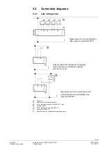
5.1.1 Low voltage side
A6
PPS (point-to-point interface) for the connection of the room unit and, if required,
for the external switch for operating mode changeover
MD Ground for the point-to-point interface
B3
Connection for d.h.w. temperature sensor (only with RVP211)
B9 Connection for outside sensor
B1
Connection for flow or boiler temperature sensor
M
Ground for sensors and changeover contact
5.1.2 Mains voltage side
L
Phase conductor AC 230 V
N
Neutral conductor AC 230 V
F1/F4 Input for Y1/K4
Y1/K4 Valve OPEN (flow temperature control) or burner ON (boiler temperature control)
F2
Input for Y2
Y2
Valve CLOSED (flow temperature control)
F3
Input for Q1
Q1
Heating circuit pump ON
L
Phase conductor AC 230 V
N
Neutral conductor AC 230 V
F1/F4 Input for Y1/K4
Y1/K4 Valve OPEN (flow temperature control) or burner ON (boiler temperature control)
F2
Input for Y2
Y2
Valve CLOSED (flow temperature control with three-position actuator)
F3
Input for Q1 and Q3/Y3
Q1
Heating circuit pump ON
Q3/Y3 D.h.w. charging pump or changeover valve ON
5.1.3 Auxiliary
terminals
In addition to the standard connection terminals, the base accommodates three
auxiliary terminals: M; N and
.
RVP201
RVP211


