background image

4/46

Siemens

Heating controllers RVP201 and RVP211

CE1P2464D

Building Technologies

Contents

2017-07-21

3.4.1

Boost  heating ................................................................................................. 22

3.4.2

Quick setback ................................................................................................ 22

3.5

ECO automatic energy saver ......................................................................... 23

3.5.1

Fundamentals ................................................................................................ 23

3.5.2

Compensating and auxiliary variables ........................................................... 23

3.5.3

Heating  limit ................................................................................................... 24

3.5.4

Mode of operation of ECO function 1 ............................................................. 24

3.5.5

Mode of operation of ECO function 2 ............................................................. 24

3.6

Frost protection for the plant and the building ................................................. 24

3.6.1

Frost protection for the plant .......................................................................... 24

3.6.2

Frost protection for the building ..................................................................... 25

3.7

D.h.w.  heating ................................................................................................ 25

3.7.1

General .......................................................................................................... 25

3.7.2

Acquisition of  d.h.w. temperature ................................................................... 25

3.7.3

D.h.w. heating with charging pump ................................................................ 26

3.7.4

D.h.w. heating with changeover valve ........................................................... 27

3.7.5

Frost  protection .............................................................................................. 27

3.8

Pump  control .................................................................................................. 27

3.8.1

Pump overrun ................................................................................................ 27

3.8.2

Pump kick ...................................................................................................... 28

3.9

Interactions with room units ........................................................................... 28

3.9.1

General .......................................................................................................... 28

3.9.2

Interactions with room unit QAA50.. .............................................................. 29

3.9.3

Interactions with room unit QAW70 ............................................................... 29

4

Handling ......................................................................................................... 32

4.1

Operation ....................................................................................................... 32

4.1.1

Operating  elements ........................................................................................ 32

4.1.2

Setting and readjusting the room temperature ............................................... 33

4.1.3

Selection of operating mode .......................................................................... 34

4.2

Mounting ........................................................................................................ 34

4.2.1

Mounting  location ........................................................................................... 34

4.2.2

Mounting methods ......................................................................................... 34

4.2.3

Installation ...................................................................................................... 34

5

Engineering .................................................................................................... 35

5.1

Connection terminals ..................................................................................... 35

5.1.1

Low voltage side ............................................................................................ 35

5.1.2

Mains voltage side ......................................................................................... 35

5.1.3

Auxiliary  terminals .......................................................................................... 35

5.2

Connection diagrams ..................................................................................... 36

5.2.1

Low voltage side ............................................................................................ 36

5.2.2

Mains voltage side ......................................................................................... 37

Содержание RVP201

Страница 1: ...Edition 2 0 Controller series A CE1P2464en 2017 07 21 Building Technologies Heating Controllers RVP201 and RVP211 Basic Documentation ...

Страница 2: ...1P2464en Building Technologies 2017 07 21 Siemens Switzerland Ltd Building Technologies Group International Headquarters Gubelstrasse 22 CH 6301 Zug Tel 41 58 724 24 24 Fax 41 41 724 35 22 www siemens com sbt 2007 Siemens Switzerland Ltd Subject to change ...

Страница 3: ...Boiler temperature control with RVP201 10 2 5 3 Boiler temperature control with RVP211 d h w heating with charging pump 10 2 5 4 Boiler temperature control with RVP211 d h w heating with changeover valve 10 2 5 5 Flow temperature control with RVP211 11 3 Technical design 12 3 1 Operating modes 12 3 2 Acquisition of actual values 13 3 2 1 General remarks about faults in the measuring circuits 13 3 ...

Страница 4: ...erature 25 3 7 3 D h w heating with charging pump 26 3 7 4 D h w heating with changeover valve 27 3 7 5 Frost protection 27 3 8 Pump control 27 3 8 1 Pump overrun 27 3 8 2 Pump kick 28 3 9 Interactions with room units 28 3 9 1 General 28 3 9 2 Interactions with room unit QAA50 29 3 9 3 Interactions with room unit QAW70 29 4 Handling 32 4 1 Operation 32 4 1 1 Operating elements 32 4 1 2 Setting and...

Страница 5: ... CE1P2464en Building Technologies Contents 2017 07 21 6 Mechanical design 38 6 1 Controller 38 6 1 1 Basic design 38 6 1 2 Dimensions 38 6 1 3 Outside view 39 6 2 Time switches 39 6 2 1 General 39 6 2 2 Analog time switches AUZ3 39 7 Technical data 41 ...

Страница 6: ...6 46 Siemens Heating controllers RVP201 and RVP211 CE1P2464D Building Technologies Contents 2017 07 21 ...

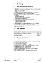
Страница 7: ...The controller features analog operating elements such as switches sliders and setting knobs with one exception the optional digital time switch Other key features operating voltage AC 230 V CE conformity overall dimensions to IEC 61554 144 96 mm 1 2 Type summary Type summary Type ref Heating controller without time switch RVP201 0 Heating controller with d h w heating without time switch RVP211 0...

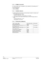
Страница 8: ...ting voltage AC 24 230 V Maximum running time 6 minutes ideally 2 to 3 minutes For two position control electro thermal actuators with the following features are suited Operating voltage AC 24 230 V Running time 8 16 minutes 1 3 4 Product documentation Type of documentation Document number Part number Data sheet RVP201 211 N2464 Operating Instructions languages de en fr nl sv fi da it es el B2464 ...

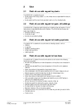
Страница 9: ...nctions The RVP201 211 is suitable for use in plants where one or several of the following functions are required Weather compensated flow or boiler temperature control without room temperature influence Weather compensated flow or boiler temperature control with room temperature influence Room temperature compensated flow temperature control Flow temperature control through modulating control of ...

Страница 10: ...oiler temperature control with RVP201 B9 A6 2462S02 Two position control acting on burner 2 5 3 Boiler temperature control with RVP211 d h w heating with charging pump B9 A6 2462S03 B3 E3 M3 Two position control acting on burner d h w heating with charging pump 2 5 4 Boiler temperature control with RVP211 d h w heating with changeover valve B9 A6 2462S04 B3 E3 Y3 Two position control acting on bur...

Страница 11: ...n con trol acting on mixing valve d h w heating with charging pump A6 Room unit B1 Boiler or flow temperature sensor B3 D h w temperature sensor B9 Outside sensor E1 Heat generating equipment boiler E2 Load room E3 D h w storage tank M1 Heating circuit pump M3 D h w charging pump N1 Controller RVP201 211 Y1 Motorized three or two position mixing valve Y3 Motorized changeover valve ...

Страница 12: ... the outside temperature while giving consideration to the building s thermal inertia ECO automatic energy saver Optional remote operation with the help of a room unit Frost protection is ensured Setback mode Continuous heating to the reduced temperature Automatic d h w heating Load dependent switching on and off of the heating in function of the outside temperature while giving consideration to t...

Страница 13: ...ith a sensing element NTC 575 at 20 C The controller automatically identifies the type of sensor connected If a fault occurs in the outside sensor s measuring circuit the control responds as fol lows Plants with a room temperature sensor The controller switches to pure room temperature control Plants without a room temperature sensor The controller ensures control based on a fix outside temperatur...

Страница 14: ...perature sensor The lowest valid room temperature setpoint always represents the minimum setpoint for the frost protection for the plant even if a lower value has been set as the setpoint for the reduced temperature The setpoint for the frost protection for the plant is 5 C fixed value 3 3 2 Heating program The controller has a plug in type time switch for entering a 24 hour or weekly heating prog...

Страница 15: ...ol the RVP201 211 only uses the composite outside temperature TA B9 2462B01 TA k t TAD TAM Generation of composite and attenuated outside temperature TA Actual outside temperature TAD Attenuated outside temperature TAM Composite outside temperature kt Building time constant 0 5 10 15 20 25 TAD TAM t 2522D17 TA TA Development of actual composite and attenuated outside temperature TA Actual outside ...

Страница 16: ...nge wR of the room temperature setpoint is calculated in a static state using the following formula Gain factor wR wR xR 10 2462D06 s Impact of change of room temperature setpoint on the flow tempera ture setpoint wR Change of room temperature setpoint s Slope of heating curve wVT Change of flow temperature setpoint The change wVT of the flow temperature setpoint is calculated using the following ...

Страница 17: ... can be infinitely set around this point in the range 0 25 4 The substitute line of each heating curve runs through the tilting point and intersects its heating curve at an outside temperature of 0 C Its slope is calculated as follows s TV TAM and is adjusted on the controller The substitute lines are needed because the heating curve is slightly inflected This is required to compensate for the non...

Страница 18: ... authority of room tem perature deviation Multiplier E Authority gain factor of room temperature deviation H Heating curve I Integrator with limitation L Limiter s Slope of heating curve TAM Composite outside temperature TRw Room temperature stepping TRx Room temperature TVw Flow temperature setpoint The setpoint is generated based on the setpoint actual value deviation of the room temperature Als...

Страница 19: ... the room temperature Prerequisites for this type of control Room unit connected No outside sensor connected or Room authority set to 100 if an outside sensor is connected If no outside sensor is connected the setting potentiometer for the room authority is inactive The compensating variable used for room temperature compensated control is the setpoint actual value deviation of the room temperatur...

Страница 20: ...erature 3 3 7 Control process If the flow temperature deviates from the setpoint a two port seat valve or mixing valve three port seat or slipper valve driven by an electric actuator is controlled in a step wise fashion until the setpoint is reached The RVP201 211 is suited to drive electric or electro hydraulic actuators with a running time of 2 to 3 minutes whereby a maximum running time of 6 mi...

Страница 21: ... be maintained If however the boiler temperature falls below 5 C the burner will always be switched on until the boiler temperature has exceeded the minimum limit value of the boiler tem perature by the amount of the switching differential This always ensures a minimum boiler temperature of 5 C 3 3 8 Limitations The maximum limitations are no safety functions For this purpose devices such as therm...

Страница 22: ...ure setpoint Also the selected room authority is considered when generating this setpoint The boost of 5 K is factory set When the room temperature is only 0 25 K below the normal temperature setpoint the boost function will be disabled Boost heating can be provided only if a room temperature sensor room unit is used It is active independent of the setting of potentiometer E t 2464D01 wR xR TR 5 K...

Страница 23: ...ive Normal mode Fehler Es ist nicht möglich durch die Bearbeitung von Feldfunktionen Objekte zu erstellen Inactive Setback mode Active Protection mode Active Manual operation Fehler Es ist nicht mög lich durch die Bearbeitung von Feldfunk tionen Objekte zu erstellen Inactive D h w heating only only with RVP211 Inactive ECO automatic energy saver active means Seat or slipper valve closed or burner ...

Страница 24: ...N of 20 C and an ECO temperature TECO of 5 K give a heating limit of 15 C 3 5 5 Mode of operation of ECO function 2 ECO function 2 operates as an automatic 24 hour limit switch The heating will be switched off mixing valve closes or burner off heating circuit pump off when the actual or the composite outside temperature exceeds the heating limit It is switched on again as soon as all three outside...

Страница 25: ...tial of 1 K 3 6 2 Frost protection for the building Frost protection for the building protects the rooms from excessively low temperatures It acts in all operating modes as a minimum limitation of the room temperature It can be achieved with or without room unit provided the heating curve slope is correctly set The frost protection for the building is given higher priority over the ECO automatic e...

Страница 26: ...on boiler temperature control To ensure fast d h w heating the other heating loads can be restricted during the time the d h w is heated priority The following choices are available Absolute priority During d h w heating the heating circuit pump is locked which means that all other heating loads will be dead In the case of underfloor or ceiling heating systems as well as boiler operation ab solute...

Страница 27: ...RVP201 and RVP211 CE1P2464en Building Technologies 3 Technical design 2017 07 21 t 2462D03 x TBW w SD 5 K ON OFF SD Switching differential t Time TBW D h w temperature w Setpoint of d h w temperature x Actual value of d h w temperature ...

Страница 28: ...errun time lies below the d h w temperature pump overrun will be stopped prematurely that is before the 6 minutes have elapsed This prevents the d h w from cooling down un necessarily When using a thermostat for the d h w temperature pump overrun will be stopped when the boiler temperature lies below the adjusted d h w temperature setpoint 3 7 5 Frost protection The d h w storage tank is protected...

Страница 29: ...f by ECO 4 On completion of d h w heating the heating circuit pump is immediately activated this may lead to a temperature rise in the heating circuit 5 Protection against discharging active 6 Mixing valve closes 3 8 2 Pump kick Periodic pump run is provided to prevent pump seizure during longer off periods e g in the summer After the last regular use of the pump the pump kick is provided for one ...

Страница 30: ...le the QAA50 to act on the controller the latter must meet the following oper ating conditions Automatic mode A6 MD not bridged that is external changeover switch if present must be open The actions of the QAA50 operating mode slider on the RVP201 211 are as follows Operating mode QAA50 Operating mode RVP201 211 Automatic mode or temporary overriding with QAA50 economy button possible Normal or se...

Страница 31: ...actions of the QAW70 operating mode buttons on the RVP201 211 are as follows Operating mode QAW70 Operating mode RVP201 211 Automatic mode or temporary overriding with QAW70 economy button possible Normal or setback mode depending on economy button per manent overriding Protection mode With the setting knob of the QAW70 only the room temperature setpoint of normal heating set on operating line 1 c...

Страница 32: ...s the time switch of the RVP201 211 11 Entry weekday 1 7 Overrides the time switch of the RVP201 211 12 Entry time of day Overrides the time switch of the RVP201 211 13 D h w temperature with sensor only Display only with the RVP211 not available with the RVP201 14 Boiler temperature Display only with the setting on the RVP201 211 15 Flow temperature Display only with the setting on the RVP201 211...

Страница 33: ...urve 5 Setting knob for setback to the reduced temperature 6 Setting knob for the d h w temperature not available with the RVP201 7 Setting knob for the normal temperature the zero setting corresponds to a room temperature of 20 C Override 2464Z07 1 2 3 6 5 4 1 Coding switches 2 Setting potentiometer for the switching differential 3 Setting potentiometer for the ECO temperature 4 Setting potentiom...

Страница 34: ...ld be used Potentiometer Function Setting range Guide values notes Switching differen tial with two position control 1 20 K Effective only with burner control guide value 6 K Effect of room tem perature on flow temperature control 0 100 authority Guide value for plants with outside sensor 50 Quick setback is active inactive Off Off quick setback is inac tive Heating limit for ECO automatic energy ...

Страница 35: ...unted in a dry location such as the boiler room The permissible ambient temperature in operation is 0 50 C The RVP201 211 can be mounted as follows In the control panel on the inner wall or on a top hat rail On a panel front In the control panel front In the sloping front of a control desk 4 2 2 Mounting methods The RVP201 211 is designed for three different mounting methods Wall mounting the base...

Страница 36: ...ge side L Phase conductor AC 230 V N Neutral conductor AC 230 V F1 F4 Input for Y1 K4 Y1 K4 Valve OPEN flow temperature control or burner ON boiler temperature control F2 Input for Y2 Y2 Valve CLOSED flow temperature control F3 Input for Q1 Q1 Heating circuit pump ON L Phase conductor AC 230 V N Neutral conductor AC 230 V F1 F4 Input for Y1 K4 Y1 K4 Valve OPEN flow temperature control or burner ON...

Страница 37: ...1 2 S1 2462A02 External switch for changeover of operating mode can also be connected in parallel with the room unit 2462A03 3 B3 F3 T Measurement of d h w temperature with a thermostat and an intermediate relay only with RVP211 A6 Room unit B1 Flow or boiler temperature sensor B3 D h w temperature sensor with RVP211 only B9 Outside sensor F3 D h w thermostat only with RVP211 N1 Controller RVP201 ...

Страница 38: ...1 2 F1 F4 F1 F2 E1 2462A05 Connection of burner boiler temperature control 3 F1 F4 2462A06 Connection of two position actuator flow temperature control Y3 Q3 Y3 4 F3 2462A07 Connection of actuator for changeover valve only with RVP211 E1 Burner F1 Thermal reset limiter thermostat F2 Manual reset safety limit thermostat M1 Heating circuit pump M3 D h w charging pump only with RVP211 N1 Controller R...

Страница 39: ...a time switch RVP201 0 or RVP211 0 the space for the time switch is covered up with a hinged cover If a time switch is fitted at a later time the appropriate hole in the cover must be cut out with a knife The RVP201 211 can be fitted in three different ways Wall mounting Rail mounting Flush panel mounting in that case the front panel may have a maximum thickness of 3 mm To make certain the control...

Страница 40: ...iring is required The following types of time switches are available Analog 24 hour time switch AUZ3 1 Analog weekly time switch AUZ3 7 6 2 2 Analog time switches AUZ3 The analog time switches AUZ3 1 and AUZ3 7 are equipped with a quartz clock Back up is 12 hours When power returns after a power failure the clock will be readjusted Automatic read justment can be aborted by briefly setting the oper...

Страница 41: ...switch AUZ3 1 with a heating period from 6 00 to 22 00 1 Time indicator 2 Switching dial 3 Hand 4 Setting aid 5 Tappet tilted inward 6 Tappet tilted outward The weekly time switch has a 7 day switching dial It carries 84 pairs of tappets which means 12 pairs of tappets or 24 individual tappets per day The resolution is thus one hour However since for mechanical reasons at least two tappets need to...

Страница 42: ...ture 10 100 C ECO heating limit 10 8 K referred to normal setpoint Authority of room temperature 0 100 Switching differential with 2 position control 1 20 K Analog time switches 12 hours Product standard EN 60730 1 Automatic electrical controls for household and similar use Electromagnetic compatibility Applications For use in residential commerce lightindustrial and industrial environments EU con...

Страница 43: ...1 Operation EN 60721 3 3 Transport EN 60721 3 2 Storage EN 60721 3 1 Climatic conditions class 3K5 class 2K3 class 1K3 Temperature 0 50 C 25 70 C 20 65 C Humidity 95 r h non condensing 95 r h 95 r h non condensing Mechanical conditions class 3M2 class 2M2 class 1M2 Use above sea level Max 3000 m above sea level ...

Страница 44: ...aver 23 ECO function 1 24 ECO function 2 24 economy button 30 31 electric actuator 20 electric or electro hydraulic actuators 20 electro thermal actuators 20 enabling of d h w heating 26 environmental conditions 43 external switch 13 35 37 F factory settings 34 faults in the measuring circuits 13 features 7 field of use 9 fixing screw 39 frost protection for the boiler 21 frost protection for the ...

Страница 45: ...perature 34 reference room 20 required operating mode 35 resolution 41 room authority 19 room temperature 13 room temperature compensated control 18 19 room unit QAA50 30 room unit QAW70 30 room units 13 S safety function 21 35 sealed 39 sensing element 13 sensors flow or boiler temperature 13 setback mode 12 setpoint actual value deviation of room temperature 19 setpoint adjustments 14 setting po...

Страница 46: ...464en Building Technologies Index 2017 07 21 Siemens Switzerland Ltd Building Technologies Group International Headquarters Gubelstrasse 22 CH 6301 Zug Tel 41 41 724 24 24 Fax 41 58 724 35 22 www siemens com sbt 2007 Siemens Switzerland Ltd Subject to change ...

Отзывы: