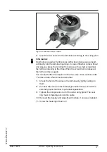
background image

14

MAN-100472

RD150 - Operating Instructions

57030-EN-180717

2

1

3

Fig. 7: RD150 for tube mounting
1  4 screws M6 x 100

2  Mounting brackets

3  Tube (diameter 1" to 2")

The RD150 is also available with a plastic housing for panel mount-

ing. The housing is fastened to the rear of the panel by means of the 

supplied screw clamps.

4

5

1

2

3

Fig. 8: RD150 for panel mounting
1  Inspection window

2  Front panel

3  Screw clamp

4 Housing

5  Plug connector

Front panel mounting

Содержание RD150

Страница 1: ...Operating Instructions 07 2018 Indication and adjustment RD150 4 20 mA HART External display and adjustment unit ...

Страница 2: ...2 MAN 100472 RD150 Operating Instructions 57030 EN 180717 ...

Страница 3: ...g to power supply 15 5 1 Preparing the connection 15 5 2 Connection technology and steps 16 5 3 Wiring plan 18 5 4 Connection HART standard 18 5 5 Connection HART multidrop 19 5 6 Connection signal conditioning instrument four wire sensor 19 5 7 Connection example 20 5 8 Switch on phase 20 6 Set up with the display and adjustment module 21 6 1 Short description 21 6 2 Insert display and adjustment...

Страница 4: ...isposal 37 10 Supplement 38 10 1 Technical data 38 10 2 HART communication 41 10 3 Dimensions 42 10 4 Trademark 45 Safety instructions for Ex areas Take note of the Ex specific safety instructions for Ex applications These instructions are attached as documents to each instrument with Ex approval and are part of the operating instructions manual Editing status 2018 07 12 ...

Страница 5: ...e to the qualified personnel and implemented 1 3 Symbols used Information tip note This symbol indicates helpful additional information Caution If this warning is ignored faults or malfunctions can result Warning If this warning is ignored injury to persons and or serious damage to the instrument can result Danger If this warning is ignored serious injury to persons and or destruction of the instr...

Страница 6: ...lying with all prevailing regulations and directives The instrument must only be operated in a technically flawless and reliable condition The operator is responsi ble for the trouble free operation of the instrument When measuring aggressive or corrosive media that can cause a dangerous situation if the instrument malfunctions the operator has to implement suitable measures to make sure the instr...

Страница 7: ...strumentation The device fulfils the requirements of the following NAMUR recom mendations NE 21 Electromagnetic compatibility of equipment NE 53 Compatibility of field devices and display adjustment components For further information see www namur de 2 7 Installation and operation in the USA and Canada This information is only valid for USA and Canada Hence the follow ing text is only available in...

Страница 8: ... different housing materials see chapter Technical data The instrument is optionally available with or without display and adjustment module This operating instructions manual applies to the following instrument versions Software from 1 10 00 Hardware from 1 00 00 The scope of delivery encompasses RD150 Display and adjustment module optional Mounting accessories optional Documentation This operati...

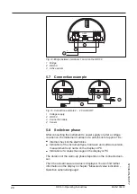
Страница 9: ... RD150 integrated in the display and adjustment module 4 5 3 1 2 Fig 2 Connection of the RD150 to the sensor adjustment via the display and adjustment module 1 Voltage supply Signal output sensor 2 RD150 3 Display and adjustment module 4 4 20 mA HART signal cable 5 Sensor The sensor adjustment is carried out via a PC with PACTware DTM 4 5 6 3 2 1 Fig 3 Connection of the RD150 to the sensor and the...

Страница 10: ...endly recyclable cardboard For special versions PE foam or PE foil is also used Dispose of the packaging material via specialised recycling companies Transport must be carried out in due consideration of the notes on the transport packaging Nonobservance of these instructions can cause damage to the device The delivery must be checked for completeness and possible transit damage immediately at rec...

Страница 11: ...ocal Display Interface is used for measured value indication adjustment and diagnosis It can be inserted into the sensor or the external display and adjustment unit and removed at any time You can find additional information in the operating instructions manual LG Local Display Interface Document ID 43838 Display and adjustment module ...

Страница 12: ... to outdoor installations in areas where high humidity is expected e g through cleaning processes and on cooled or heated vessels To maintain the housing protection make sure that the housing lid is closed during operation and locked if necessary Make sure that the degree of contamination specified in chapter Technical data meets the existing ambient conditions 4 2 Mounting instructions The RD150 ...

Страница 13: ...sists of an adapter plate and four mounting screws M6 x 12 The adapter plate is screwed to the base of RD150 by the user 3 2 1 Fig 6 RD150 with aluminium and stainless steel housing for carrier rail mount ing 1 Base 2 Adapter plate with screws M6 x 12 3 Carrier rail The RD150 for tube mounting is supplied with unassembled mounting accessories The kit consists of two pairs of mounting brackets and ...

Страница 14: ... brackets 3 Tube diameter 1 to 2 The RD150 is also available with a plastic housing for panel mount ing The housing is fastened to the rear of the panel by means of the supplied screw clamps 4 5 1 2 3 Fig 8 RD150 for panel mounting 1 Inspection window 2 Front panel 3 Screw clamp 4 Housing 5 Plug connector Front panel mounting ...

Страница 15: ...nit can be lower under nomi nal load with a sensor current of 20 5 mA resp 22 mA in case of fault message Voltage loss on the RD150 see supply circuit in chapter Techni cal data You can find information on the load resistance in chapter Technical data voltage supply of the respective sensor The instrument is connected with standard two wire cable without screen If electromagnetic interference is e...

Страница 16: ...plants for cathodic corrosion protec tion it must be taken into account that significant potential differences exist This can lead to unacceptably high currents in the cable screen if it is grounded at both ends 5 2 Connection technology and steps The voltage supply and signal output are connected via the spring loaded terminals in the housing Connection to the display and adjustment module or to ...

Страница 17: ...terminal opening is then free When the screwdriver is released the terminal closes again You can find further information on the max wire cross section under Technical data Electromechanical data 7 Check the hold of the wires in the terminals by lightly pulling on them 8 Connect the screen to the internal ground terminal connect the external ground terminal to potential equalisation 9 Tighten the ...

Страница 18: ...power supply 1 3 2 4 3 1 2 Fig 11 Wiring plan RD150 for 4 20 mA sensors panel mounting 1 To the sensor 2 Ground terminal in the switching cabinet for connection of the cable screen 3 For power supply 5 4 Connection HART standard The following illustration shows in a simplified way the use of RD150 in conjunction with a HART sensor 1 2 3 Fig 12 Installation example RD150 in conjunction with an indi...
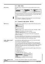
Страница 19: ...ig 13 Installation example with one RD150 for several sensors in a Multidrop system 1 Sensor 2 RD150 3 Voltage supply Processing 5 6 Connection signal conditioning instrument four wire sensor The following illustration shows the simplified the connection of RD150 to a four wire sensor with active 4 20 mA output For this terminals 1 and 4 on RD150 must be bridged Four wire sensor with ac tive 4 20 ...

Страница 20: ...sor 5 8 Switch on phase After connecting the instrument to power supply or after a voltage recurrence the instrument carries out a self check for approx 10 s Internal check of the electronics Indication of the instrument type hardware and software version measurement loop name on the display or PC Indication of a status message on the display or PC The duration of the warm up phase depends on the ...

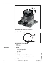
Страница 21: ...y and adjustment module The display and adjustment module can be inserted into the RD150 and removed again at any time It is not necessary to interrupt the power supply Note The operation of a display and adjustment module with integrated Bluetooth function is not supported by RD150 Proceed as follows for mounting the display and adjustment module 1 Unscrew the housing lid 2 Place the display and ...

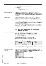
Страница 22: ...3 Adjustment system 1 2 Fig 17 Display and adjustment elements 1 LC display 2 Adjustment keys OK key Move to the menu overview Confirm selected menu Edit parameter Save value key Change measured value presentation Select list entry Select menu items in the quick setup menu Select editing position key Key functions ...

Страница 23: ...pressing of a key an automatic reset to measured value indication is triggered Any values not confirmed with OK will not be saved 6 4 Measured value indication Selection of national language With the key you can move between five different views First view Display value 1 in big lettering TAG number Second view Display value 1 a bargraph corresponding to the 4 20 mA value TAG number Third view Dis...

Страница 24: ...acture instrument features For optimum adjustment of the instrument the individual submenu items should be selected one after the other in the main menu item Setup and provided with the correct parameter values In the menu item Measurement loop name you edit a twelve digit measurement loop designation label You can enter an unambiguous designation for the measured value e g the measurement loop na...

Страница 25: ... has a backlight for the display In this menu item you can switch on the lighting You can find the required operating voltage in chapter Technical data The lighting is switched off in delivery status Note The lighting switches off automatically when the current in the signal circuit is lower than 4 mA It switches on automatically when the current in the signal circuit is 4 mA or higher To damp pro...

Страница 26: ...trument parameters against unauthorized modification The PIN is activated deactivated permanently With active PIN only the following adjustment functions are possible without entering a PIN Select menu items and show data Read data from the sensor into the display and adjustment module Caution When the PIN is active adjustment via PACTware DTM as well as other systems is also blocked The PIN numbe...

Страница 27: ...t be available or some may be differently assigned Reset Setup Menu item Parameter Default value Measurement loop name Display Display Language English Order specific Displayed value Signal current Backlight Switched off Damping Integration time 0 s Scaling Scaling size Scaling format 20 mA correspond to 100 00 4 mA correspond to 0 00 Lock adjustment Released Reset Additional settings Menu item Pa...

Страница 28: ...y Master The parameter HART address defines the address of the sensor RD150 communicates with via HART The factory setting is Secondary Master and the address 00 In this menu item you can read out the instrument name and the instrument serial number In this menu item the hardware and software version of the sensor is displayed In this menu item the date of the factory calibration of the instru men...

Страница 29: ...me or the tank or product designation In digital systems and in the documentation of larger plants a singular desig nation must be entered for exact identification of individual measuring points The available digits include Letters from A Z Numbers from 0 9 Special characters In this menu item the unit of the PV Primary Value adjusted on the sensor is displayed e g bar The selection determines the...

Страница 30: ...item Lower Range and confirm with OK 2 Edit the percentage value with OK and set the cursor to the requested position with 3 Edit the value with OK and set the cursor to the requested posi tion with 4 Set the requested value with and store with OK 5 With ESC you can return to the menu overview Setup The adjustment of the Lower Range is hence finished To damp process dependent measured value fluctu...

Страница 31: ...the interface adapter to the device Parameter adjustment options RD150 Sensor 3 1 2 Fig 18 Connection of the PC via interface adapter 1 USB cable to the PC 2 Interface adapter 3 RD150 The PC is connected via a HART modem to the sensor side of the RD150 Parameter adjustment options Sensor Via interface adapter Via HART modem ...

Страница 32: ...CTware and a suitable instrument driver DTM according to FDT standard are required The available DTMs are compiled on a DVD The DTMs can also be integrated into other frame applications according to FDT standard Note To ensure that all instrument functions are supported you should always use the latest DTM Furthermore not all described functions are included in older firmware versions You can down...

Страница 33: ...ured value and echo curves in the DTM Furthermore a tank calculation program as well as a multiviewer for indication and analysis of the saved measured value and echo curves are available The supplied DVD includes the respective device DTM How ever you can also download the DTM from our homepage www siemens com sitranslg 7 3 Saving the parameterisation data We recommend documenting or saving the p...

Страница 34: ...of the respective sensor The following table shows the error codes and text messages of the RD150 and gives information on the cause and removal Code Text message Cause Rectification S003 CRC error CRC error during self check Carry out a reset Send instrument for repair F008 Sensor not found Sensor in boot phase HART communica tion malfunctioning Check sensor connection Check HART address sensor F...

Страница 35: ... another software update F037 RAM defective Error of the RAM in the internal data memory Switch the instrument off and on Carry out reset to default setting Send instrument for repair F040 General hardware error Hardware error Switch the instrument off and on Carry out reset to default setting Send instrument for repair S053 Sensor measuring range too small Sensor measuring range not read correctl...

Страница 36: ...teness 8 4 Software update The following components are required to update the sensor soft ware Sensor Voltage supply PC with PACTware Current sensor software as file You can find the actual sensor software as well as detailed infor mation of the procedure in the download area on our homepage www siemens com sitranslg You can find information about the installation in the download file Caution Ins...

Страница 37: ...ies We use recyclable materials and have designed the electronics to be easily separated WEEE directive 2002 96 EG This instrument is not subject to the WEEE directive 2002 96 EG and the respective national laws Pass the instrument directly on to a spe cialised recycling company and do not use the municipal collecting points These may be used only for privately used products according to the WEEE ...

Страница 38: ...als Ex d version Ʋ Ʋ Inspection window in housing cover in version with display and adjust ment module Single pane safety glass Ʋ Ʋ Cable gland Seal insert Brass nickel plated NBR Materials for carrier rail mounting Ʋ Ʋ Adapter plate housing side 316 Ʋ Ʋ Adapter plate carrier rail side Zinc die casting Ʋ Ʋ Mounting screws 316 Materials for tube mounting Ʋ Ʋ Brackets StSt Ʋ Ʋ Mounting screws StSt M...

Страница 39: ...ce temperature 20 C Measuring range loop current 3 5 22 5 mA Deviation 0 1 of 20 mA Temperature coefficient 0 1 of the span 10 K Interval 250 ms Display and adjustment module Display element Display with backlight Measured value indication Ʋ Ʋ Number of digits 5 Adjustment elements Ʋ Ʋ 4 keys OK ESC Protection rating Ʋ Ʋ unassembled IP 20 Ʋ Ʋ mounted in the housing without lid IP 40 Materials Ʋ Ʋ ...

Страница 40: ...x 1 5 NPT Ʋ Ʋ Blind plug M20 x 1 5 NPT Ʋ Ʋ Closing cap NPT Connection terminals Ʋ Ʋ Type Spring loaded terminal Ʋ Ʋ Stripping length 8 mm Wire cross section of the connection cable according to IEC 60228 Ʋ Ʋ Massive wire stranded wire 0 2 2 5 mm AWG 24 14 Ʋ Ʋ Stranded wire with end sleeve 0 2 1 5 mm AWG 24 16 Electromechanical data Panel mounting Terminals plug connector Ʋ Ʋ Type Spring loaded ter...

Страница 41: ...e superimposed on the direct current in the wire pair of the field instrument The average value of the superimposed signal is zero For that reason the 4 20 mA signal is not influenced by the simultaneous digital data transmission Supported HART commands Command no Command name Description 0 Read Unique Identifier Sensor identification 1 Read primary variable Primary Value with unit 3 Read current ...

Страница 42: ...m 3 03 69 mm 2 72 86 mm 3 39 82 mm 3 23 97 mm 3 82 6 5 mm 0 26 97 mm 3 82 Fig 21 RD150 with plastic housing RD150 plastic housing panel mounting 72 5 mm 2 85 72 5 mm 2 85 78 2 mm 3 08 22 5 mm 0 89 70 mm 2 76 77 mm 3 03 67 mm 2 64 56 mm 2 20 76 mm 2 99 Fig 22 RD150 with plastic housing for panel mounting ...

Страница 43: ... 3 39 75 2 mm 2 95 87 mm 3 43 82 mm 3 23 97 mm 3 82 5 mm 0 2 97 mm 3 82 Fig 23 RD150 with Aluminium housing RD150 stainless steel housing precision casting ø 86 mm 3 39 75 mm 2 95 89 mm 3 49 82 mm 3 23 97 mm 3 82 5 mm 0 2 97 mm 3 82 Fig 24 RD150 with stainless steel housing precision casting ...

Страница 44: ... 23 97 mm 3 82 7 mm 0 28 11 mm 0 43 82 mm 3 23 97 mm 3 82 Fig 25 Adapter plate for carrier rail mounting of RD150 ø 29 60 mm 1 14 2 36 82 mm 3 23 15 mm 0 59 97 mm 3 82 20 mm 0 79 M6 2 mm 0 08 20 mm 0 79 2 mm 0 08 20 mm 0 79 48 84 mm 1 89 3 31 Fig 26 Brackets for tube mounting of RD150 ...

Страница 45: ...45 MAN 100472 RD150 Operating Instructions 57030 EN 180717 10 4 Trademark All the brands as well as trade and company names used are property of their lawful proprietor originator ...

Страница 46: ... Connection Cable 15 Steps 16 Technology 16 Copy sensor settings 27 D Damping 25 30 Default values 27 Display lighting 25 E Error codes 34 G Grounding 16 H HART mode 28 I Instrument versions 8 L Lock adjustment 26 M Modes 10 Mounting Carrier rail 12 Front panel 14 Position 12 Tube 13 R Recycling 37 Repair 36 Reset 27 S Scaling 26 Set display parameters 25 T Type label 8 V Voltage supply 15 W WEEE ...

Страница 47: ...Notes 47 MAN 100472 RD150 Operating Instructions 57030 EN 180717 ...

Страница 48: ...ox 4225 Peterborough ON K9J 7B1 Canada email techpubs smpi siemens com www siemens com processautomation Subject to change without prior notice MAN 100472 Rev 1 0 Siemens AG 2018 For more information www siemens com level www siemens com weighing Printed in Canada ...

Отзывы: