802-9081.9 • INSTALLATION AND OPERATING INSTRUCTIONS • NXPLUS C • Revision 11
113/293
Installation
Busbars (overview)
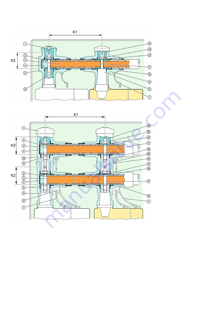
Fig. 70:
Busbar for busbar current up to 1250 A
Fig. 71:
Busbars for busbar current 1600, 2000 and 2500 A
①
Cap
②
Contact half-shell
③
Busbar
④
Adjustment component
⑤
End adapter
⑥
Busbar insulation
⑦
Earthing cable
⑧
Bushing
⑨
Earthing connection
⑩
Cross adapter
⑪
Threaded stud M12/M16
⑫
Conical spring washer,
DIN 6796-12
⑬
Hexagon nut, ISO 4032-M 12
⑭
Screw-type cone
⑮
Coupling end adapter
⑯
Copper washer, galvanized
⑰
Lock washer
⑱
Connection stud
⑲
Coupling cross adapter
⑳
Adapter lip


