background image

29

3 Operating the SAMMS-LV Device

Function

Number

Function Description

 Range

Step Size

Default Value

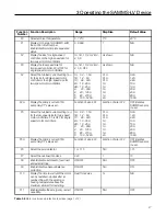
F18

Display the elapsed motor running time

in tens of hours.

0.0 - 6553 (x 10 hr.)

0.1x10hr.

up to 999.9,

1x10hr.

up to 6553

N/A

F19

Display the number of motor starts in

tens of hours.

0.0 - 6553 (x 10)

0.1x10

up to 999.9,

1x10

up to 6553

N/A

F20

Display the number of overload trips.

0 - 9999

1

N/A

F21

Reset motor data. Zeroes the elapsed

running time, the number of starts, and

the number of overload trips.

N/A

N/A

N/A

F22

Set process current warning

0-100% I

1% I

OFF

F23

Jam protection

ON/OFF

N/A

ON

F23A

Select jam pickup current

120-400% I

5%

200%

F24

Loss of Load

ON/OFF

N/A

ON

F24A

Select loss of load pickup current

20-95% of running

current

5%

50%

F25

Display percentage of motor winding

temperature

0 to 250%

1%

N/A

F26

Select baud rate

2400/4800/9600

N/A

4800

F27

Select address

1-224

1

200

FLC

FLC

FLC

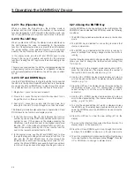
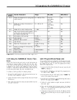
3.28 Using the SAMMS-LV Device Func-

tions

This section lists the 28 major motor control and protection

functions and several related functions (F0-F27, F4A, F5A,

F12A, F23A, and F24A) and how to use them. The functions

available for each version of the SAMMS-LV device are shown

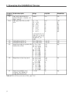
in table 3.7. Table 3.8 provides a description of each function

and its associated range, step size, and default value.

To access a function perform the following steps:

1. Connect the HHC’s cable to the communications port on

the front of the SAMMS-LV device.

2. Locate the desired function using the (F)unction and UP and

DOWN keys.

3. Then locate and follow the steps provided with the function

you wish to perform.

3.28.1 Program Mode/Passwords

To access the functions in program mode, the user is required

to enter a password. The default password is “0000,” and may

be changed at any time. To enter the password and have

access to program mode:

1. Press and hold the (F)unction key for several seconds until

“dISP”

 is displayed.

2. Press the UP or DOWN key to change to the program mode.

The display reads 

“Prog.”

3. Press the ENTER key, and the display shows 

“HHH0,”

 the

prompt for entering the password.

4. Press the UP or DOWN key to select the first digit, then press

ENTER. The display reads 

“HH0-.”

5. Continue to select password digits and press ENTER to

enter each digit.

6. After correctly entering the four digit password, the display

reads 

“- - - -,”


and pressing ENTER gives access to the

functions in program mode.

7. If the password was entered incorrectly, the display will read

“Err.”

 Press the ENTER key to return to program mode and

try again.

Table 3.8

 Motor control and protection functions (page 3 of 3)

Содержание MCC-3298

Страница 1: ...Manual No MCC 3298 SAMMS LV Siemens Advanced Motor Master System for Low Voltage Motors User s Manual 1 2 3 4 5 6 7 8 9 10 11 12 13 14 15 16 ...

Страница 2: ...ition he has the following qualifications a is trained and authorized to de energize clear ground and tag circuits and equipment in accordance with established safety practices b is trained in the proper care and use of protective equipment such as rubber gloves hard hat safety glasses or face shields flash clothing etc in accordance with established safety practices c is trained in rendering firs...

Страница 3: ... 11 Motor Ambient Temperature 17 3 12 Protection Curves and Overload Classes 17 3 13 Ultimate Trip Level and Service Factor 22 3 14 Phase Unbalance 22 3 15 Dual Overload Protection SAMMS LVX Only 22 3 16 Jam Protection SAMMS LVX Only 22 3 17 Loss of Load Protection Warning SAMMS LVX Only 22 3 18 Process Current Warning SAMMS LVX Only 22 3 19 Stator Protection 23 3 20 Repetitive Starts 23 3 21 Star...

Страница 4: ...oided may result in minor or moderate injury Dangerous Procedures In addition to other procedures described in this manual as dangerous user personnel must adhere to the following 1 Always work on de energized equipment Always de ener gize a breaker or contactor and remove it from the equip ment before performing any tests maintenance or repair 2 Alwaysperformmaintenanceonequipmentemployingsprings...

Страница 5: ...rotection device that incorporates protection tailored to the special characteristics of low voltage motors The SAMMS LV system includes a microprocessor based SAMMS LV device which receives signal inputs from a set of current transformers either 3 1Ø or 1 3Ø and power input from a 12 volt tap on the controller s control power transformer To perform certain monitoring and setup activities a Hand H...

Страница 6: ...MS LVE accepts two remote inputs SAMMS LVE is a model of SAMMS LV tailored to across the line FVNR applications It provides all of the protective func tions of the SAMMS LVX device except that it has no jam protection F23 loss of load protection alarm F24 or process current warning F22 functions Functions F3 and F5 associ ated with two speed applications are not available No provi sion for automat...

Страница 7: ...iagrams When you have finished drawing the diagram the software translates the diagram into microproces sor machine code and downloads it into the SAMMS LV device s memory 1 2 5 Using the Standardized Control Panel The SAMMS LV device can be used for local and or remote control The SAMMS LVE device provides two light bars while the SAMMS LVX model provides three light bars Each model includes six ...

Страница 8: ...closed transition X Part winding X Wye delta X Full voltage part winding X Functions available see table 3 7 F0 F21 plus F25 F27 except no F3 F5 or F8 F0 F27 Ridethrough upon loss of power No Yes Ground fault protection alarm Yes Yes Programmable alarm contact No Yes Control circuits Seven preloaded selectable with HHC May download any custom across the line control circuit Any downloadable contro...

Страница 9: ...e and its peripheral devices in a motor controller Also use these guidelines to connect the motor controller to the motor When Siemens supplies a SAMMS LV device as part of a motor controller Siemens personnel install the wiring between the SAMMS LV device and its peripheral devices in the motor controller at the factory The schematic diagram used contains three components a connection diagram a l...

Страница 10: ...8 2 Installing the SAMMS LV Device Figure 2 1 Full voltage non reversing connection diagram ...

Страница 11: ...onnect the control power source to terminals 5 and 6 located on the top of the relay 2 4 4 Connecting Input and Output Devices to the SAMMS LV Device Connect your devices to the input and output connections on the SAMMS LV device as illustrated in Figure 2 2 2 4 5 Communications Connection The SAMMS LV device is equipped with an RS 485 commu nications port on the back of the device The communicati...

Страница 12: ...e ACCESS electrical distribution communications system The SAMMS LV device connects to the SEAbus RS 485 via the 5 pin plug on the Communications Module CM 1 The communications connections are illustrated in Figure 2 3 Refer to Installing the ACCESS System manual no SG 6028 for detailed information on connecting the SAMMS LV device to the ACCESS network Figure 2 3 SAMMS LV device communications co...

Страница 13: ... a lamp test If a fault or trip condition exists when you press the Reset Test pushbutton the device performs a reset instead of a lamp test 2 Continue to hold down the Reset Test pushbutton After reaching the class time duration the Impending Trip and the Phase Unbalance LEDs illuminate 3 Release the Reset Test pushbutton The Impending Trip and Phase Unbalance LEDs go off and the Overload Trip LE...

Страница 14: ...ure 3 4 for an illustration of pilot LEDs 3 5 Input Devices You can use the following input devices with the SAMMS LV device Remote AC Inputs For SAMMS LVX you can use four 120 VAC or VDC inputs for remote control or you can use two inputs for SAMMS LVE Front Panel Pushbuttons The SAMMS LV device has six front panel pushbuttons for local control of the device You must use pushbutton 1 PB1 for stop...

Страница 15: ...ith the SAMMS LV device sheet 1 local two wire remote two wire local three wire remote three wire remote two wire remote three wire SAMMS LVE has seven preloaded circuits ladder diagrams for use with across the line FVNR applications SAMMS LVX may be used with any of the circuits For details on the library of standard ladder diagrams refer to the SAMMS Standard Circuit Manual 3 6 2 Custom Ladder D...

Страница 16: ...of Load or Jam Alarm Loss of Load or Prcs Current Trip CPU Failure or Low Voltage Trip Alarm CPU Fault Ground Fault Ready Current Unbalance Impending Trip Overload Trip Incomplete Sequence External Trip Alarm Reset Test L1 L2 L3 STOP or OFF VARIABLE VARIABLE AUTO or VARIABLE OFF or VARIABLE HAND or VARIABLE VARIABLE VARIABLE STOP or OFF PB6 PB5 PB4 PB3 PB2 PB1 Figure 3 3 Ladder symbols used with t...

Страница 17: ...24 LOCAL REMOTE 3 WIRE ELECTRICALLY INTERLOCKED STOP FWD REV 2SPD 2W PB25 LOCAL 2 WIRE OFF LOW HIGH PB26 LOCAL 3 WIRE STOP LOW HIGH PB27 LOCAL 3 WIRE REMOTE 2 WIRE STOP LOW HIGH HAND OFF AUTO PB28 LOCAL REMOTE 2 WIRE STOP LOW HIGH HAND OFF AUTO PB29 LOCAL REMOTE 3 WIRE STOP LOW HIGH PB30 REMOTE 2 WIRE PB31 REMOTE 3 WIRE 2SPD 1W CT OR VT PB32 LOCAL 2 WIRE OFF LOW HIGH PB33 LOCAL 3 WIRE STOP LOW HIG...

Страница 18: ...WIRE STOP START PB58 REMOTE 2 WIRE PB59 REMOTE 3 WIRE YDC PB60 LOCAL 2 WIRE OFF ON PB61 LOCAL 3 WIRE STOP START PB62 LOCAL 3 WIRE REMOTE 2 WIRE STOP START HAND OFF AUTO PB63 LOCAL REMOTE 2 WIRE STOP HAND OFF AUTO PB64 LOCAL REMOTE 3 WIRE STOP START PB65 REMOTE 2 WIRE PB66 REMOTE 3 WIRE YDO PB67 LOCAL 2 WIRE OFF ON PB68 LOCAL 3 WIRE STOP START PB69 LOCAL 3 WIRE REMOTE 2 WIRE STOP START HAND OFF AUT...

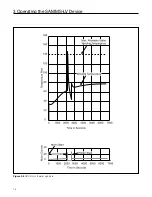
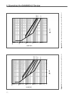
Страница 19: ...power returns within one second The ridethrough option should be used with caution because of the possibility of motor damage in the event that the contactor recloses while the motor residual voltage is significantly out of phase with the system supply voltage 3 10 Overload Protection The motor overload protection function is based on calculating the motor s winding and housing temperatures These ...

Страница 20: ...18 3 Operating the SAMMS LV Device Figure 3 5 ODP motor thermal signature ...

Страница 21: ...0 1000 100 10 1 1 1 10 SECONDS I ratio I FLC 10000 1000 100 10 1 1 1 10 SECONDS I ratio I FLC Figure 3 6 Time current characteristic curve for cold motors with SF 1 00 Figure 3 7 Time current characteristic curve for warm motors with SF 1 00 ...

Страница 22: ...re 3 9 Time current characteristic curve for warm motors with SF 1 15 Figure 3 8 Time current characteristic curve for cold motors with SF 1 15 10000 1000 100 10 1 1 1 10 SECONDS I ratio I FLC 10000 1000 100 10 1 1 1 10 SECONDS I ratio I FLC ...

Страница 23: ...s of load protection persistence delay 5 times overload class Class 5 curve Maximum stall time 25 seconds Jam protection adjustable from 120 to 400 of FLC Motor running current at full load current Loss of load adjustable from 20 to 90 of rated FLC 1 1 10 100 1000 10000 100000 Seconds Figure 3 10 Motor protection graph ...

Страница 24: ...bled HHC function F17 displays the percentage of current unbalance Both functions display OFF if phase unbalance protection is disabled 3 15 Dual Overload Protection SAMMS LVX Only Because the high speed and low speed currents differ in two speed motors different full load current settings are often required In such applications use function F5 to select the full load current for low speed operati...

Страница 25: ...pen drip proof motor Figure 3 11 Multi start scenario for an open drip proof motor 3 21 Start Inhibit When the motor temperature reaches the maximum values allowed the SAMMS LV device trips If you attempt a restart the overload LED flashes and the motor will not start until the motor winding and rotor temperatures cool down to the full load temperature HHC function F25 displays the motor winding t...

Страница 26: ...r housing tem perature but before they have cooled down to the full load temperature level 100 or below In other words an emer gency restart is a start that occurs before the restart time displayed by HHC function F10 reaches zero With the emergency restart function enabled HHC function F11 the motor can be restarted regardless of the residual heat If the SAMMS LV device performs an emergency rest...

Страница 27: ...t F9 Phase unbalance F10 Time to restart F11 Emergency restart F12 Ground fault protection or warning F12A Ground fault pickup current F13 Timer No 1 F14 Timer No 2 F15 Motor current F16 Last trip current F17 Percent unbalance current F18 Total elapsed run time on motor F19 Total number of motor starts F20 Number of overload trips F21 Reset motor data F22 Set process current warning F23 Jam protec...

Страница 28: ... the lowest numbered function F0 2 In the display mode use the UP and DOWN keys to step through the range of settings for each set point function You also use the UP and DOWN keys to step through the individual line currents and the average line current of F15 Just as the UP and DOWN keys cause the function numbers to roll over they also cause the range of settings to roll over 3 27 4 Using the EN...

Страница 29: ...ary CT s are used Function of size in F2 Function of size in F2 OFF denotes SAMMS sensors in use F5 Select the full load current setting I for the low speed size for two speed motor controllers F5 is OFF for single speed motor controllers 1A 0 3 1 5A 1B 1 2 6A 1C 4 8 24A 2A 10 36A 2B 10 45A 3 20 90A 4 40 135A 5 80 270A 6 160 540A 0 1A 0 1A 0 1A 1A 1A 1A 1A 1A 2A 0 3A 1 2A 4 8A 10A 10A 20A 40A 80A ...

Страница 30: ...conds 1 second OFF F14 Set programmable timer 2 OFF 200 seconds 1 second OFF F15 Display the average line current and the individual line currents 1A 0 0 16 8A 1B 0 0 67 1A 1C 0 0 99 9A 100 268A 2A 0 0 402A 2B 0 0 503A 3 0 0 1006A 4 0 0 1509A 5 0 0 3018A 6 0 0 6036A 0 1A 0 1A 0 1A 1A 1A 1A 1A 1A 1A 2A N A F16 Display the most recent trip current 1A 0 0 16 8A 1B 0 0 67 1A 1C 0 0 99 9A 100 268A 2A 0...

Страница 31: ... table 3 7 Table 3 8 provides a description of each function and its associated range step size and default value To access a function perform the following steps 1 Connect the HHC s cable to the communications port on the front of the SAMMS LV device 2 Locate the desired function using the F unction and UP and DOWN keys 3 Then locate and follow the steps provided with the function you wish to per...

Страница 32: ...t To enter digit First digit selected Enter following digits in the same manner 0000 9999 Password Correct Yes No ENTER ENTER UP D O W N To select function to change settings ENTER Prompt for new password UP D O W N ENTER To select digit To enter digit First digit selected Enter following digits in the same manner 0000 9999 Password entered twice UP D O W N To change password No Enter new password...

Страница 33: ... setting to the selected setting The display becomes blank while you hold down the ENTER key and the SAMMS LV device stores the new setting 5 To exit the program mode press and hold the F unction key for several seconds The display will show Prog Press the UP or DOWN key to change to the display mode 6 Press the F unction key to step through to another function 7 To enable or disable incomplete se...

Страница 34: ...r several seconds The display will show Prog Press the UP or DOWN key to change to the display mode 6 Press the F unction key to step through to another function F5 Full Load Current for Overload Relay 2 SAMMS LVX Only 1 Press the LIST key to view the active full load current setting for overload relay 2 This setting should normally be the full load current for the low speed shown on the motor nam...

Страница 35: ...ss and hold the F unction key for several seconds The display will show Prog Press the UP or DOWN key to change to the display mode 6 Press the F unction key to step through to another function F8 Autoreset SAMMS LVX Only 1 Press the LIST key to view the active autoreset setting either ON or OFF If autoreset is ON the SAMMS LV device automatically resets 30 seconds after an overload or exter nal t...

Страница 36: ...in either the program mode or the display mode 3 To change the setting press the UP or DOWN key to display the setting options then press ENTER to select the setting that is shown If the selected setting is ON skip to Step 5 4 If the selected setting is OFF the display blanks while the ENTER key is pressed When the ENTER key is released the setting is changed to OFF Skip to Step 6 5 If the selecte...

Страница 37: ...r timer 2 The default setting is OFF If the timer is not used in the control circuit OFF is displayed and the UP DOWN and ENTER keys are disabled OFF is also displayed for a setting of 0 seconds The timer may be adjusted from 0 200 seconds in one second increments 2 To change the setting you must be in program mode 3 To change the setting press the UP or DOWN key until the desired value is display...

Страница 38: ...his function 3 Press the F unction key to go to other functions F21 Reset Motor Data 1 To reset to zero the elapsed running time the number of starts and the number of overload trips press the LIST key CLr is displayed 2 Press the ENTER key SUrE is displayed 3 Press the ENTER key again to zero the motor data 4 To return to Step 1 press the LIST key at any time 5 The UP and DOWN keys are disabled f...

Страница 39: ...ns then press ENTER to select the setting that is shown The display blanks while the ENTER key is pressed 4 Return to Step 3 if you select an incorrect setting 5 To exit the program mode press and hold the F unction key for several seconds The display will show Prog Press the UP or DOWN key to change to the display mode 6 Press the F unction key to step through to another function F24A Loss of Loa...

Страница 40: ...settings until the selected setting appears on the display 4 Press the ENTER key to change the active setting to the selected setting The display becomes blank while you hold down the ENTER key and the SAMMS LV device stores the new setting 5 To exit the program mode press and hold the F unction key for several seconds The display will show Prog Press the UP or DOWN key to change to the display mo...

Страница 41: ...nce Current unbalance LED is illuminated if current unbalance exceeds 40 or it flashes if current unbalance is between 20 and 40 Current unbalance may be due to voltage or load unbalance 1 2 Correct the cause of voltage or load unbalance Verify current transformer secondary voltage is unbalanced at SAMMS LV terminals 1 2 and 3 with reference to 4 Overload Trip Indicates motor exceeded winding hous...

Страница 42: ...he source and reconnect so that the motor current only passes through the current transformer To disable incomplete sequence select F1 on the HHC press the ENTER key for one or more seconds and start the motor The incomplete sequence will remain disabled until the above procedure is repeated External Trip If the external trip LED is solidly illuminated and the motor is stopped it indicates a jam o...

Страница 43: ...LV unit is in the Auto mode Verify 115 VAC input at SAMMS LV terminals 9 10 11 and 12 with reference to 13 and at terminal 7 with reference to 13 If remote operation is intermittent verify connections are made in a manner to avoid noise interference Refer to Section 2 of this manual for instructions Improper Alarm Contact Operation Indicates connection error Verify 115 VAC at terminals 7 and 8 wit...

Страница 44: ...lete sequence Ground fault CPU fault Ready Light bar flashes timer timing Impending trip LED flashes motor temperature warning Overload trip LED flashes start inhibit CPU LED ON momentary loss of voltage Current Ranges 0 3 1 5A 1 2 6A 4 8 24A 10 36A 10 45A 20 90A 40 135A 80 270A 160 540A Overload Relay Size 1A 1B 1C 2A 2B 3 4 5 6 Permissible CT Ratios 5A secondary CT ratios functions F4A F5A Overl...

Страница 45: ...ult value 200 I Loss of load protection SAMMS LVX only Sudden decrease of motor running current Pick up current adjustable from 20 to 95 in increments of 5 of I Pick up time 360 msec Default value 50 I Process current warning SAMMS LVX only Settings from 0 to 100 of I Accuracy 5 of overload trip curve values 2 repeat accuracy Phase unbalance protection Response time after 1 second Shifted trip thr...

Страница 46: ...s contacts Statistical Data Elapsed motor running time x10 Range 0 0 to 6553 65 536 hours Unit increments 10 hours Number of motor starts x10 Range 0 0 to 6553 65 536 hours Unit increments 10 operations Number of overload trips Range 0 to 9999 Increments 1 trip Current display Overload Relay Size Current Increments 1A 0 1A 1B 0 1A 1C 0 1A 2A 1A 2B 1A 3 1A 4 1A 5 1A 6 2A Alarm Contact SAMMS LVX Onl...

Страница 47: ...z Electrostatic discharge No hardware failures at 15 kV at any point in the front of the unit Electromagnetic interference 5 kV repeated pulses per UL 991 and ANSI C37 90A Radio frequency interference Up to 95 MHz and 61 3 V M field strength Control Power Specifications Unit powered by 12 VAC 10 15 supply Power requirements 4VA Control circuit inputs 120 VAC or 125 VDC 10 15 Control circuit output...

Страница 48: ...cts Configuration SAMMS LVX Only 0 None 1 Normally Closed Contacts N C 2 Normally Open Contacts N O Alarm Contacts Output SAMMS LVX Only A Any of the Below B Impending Trip C Overload Trip D External Trip E Ground Fault F None Loss of Voltage SAMMS LVX Only L Loss of Voltage Ridethrough 0 None Ground Fault G Ground Fault Protection 0 None Control Circuit Number Control Circuit Number Loaded at Fac...

Страница 49: ...ncomplete Sequence External Trip Alarm Reset Test 1 2 3 4 5 6 7 8 9 10 11 12 13 14 15 16 2 125 6 25 6 00 3 258 266 1 010 2 50 02 375 375 5 50 5 25 4X 125 DIA X 375 DEEP FOR 6 SELF TAPPING MOUNTING SCREWS SIDE FRONT REAR OPEN OPEN 1 2 S1 1 2 3 4 5 S2 S1 1 S1 2 S2 1 S2 2 S2 3 S2 4 S2 5 NORMALLY OPEN NORMALLY CLOSED ANY OF THE BELOW IMPENDING TRIP OVERLOAD TRIP EXTERNAL TRIP GROUND FAULT SWITCH FUNCT...

Страница 50: ...8 2B 4 25 1 00 2 94 0 50 3 50 0 38 0 19 0 38 3 5 57 1 68 2 38 4 50 0 53 0 69 1 80 1 07 4 5 57 1 68 2 38 4 50 0 53 0 69 1 80 1 07 5 8 50 2 00 3 75 7 60 0 45 1 00 2 75 1 87 6 12 80 2 63 4 87 11 50 0 65 1 63 4 00 2 36 A B J J C C F I I I I E H DIA H DIA 8 32 STUD TYP 8 32 STUD TYP 0 19 x 0 30 OPEN SLOTS TYP B D A E F SAMMS Sensor sizes 5 6 SAMMS Sensor sizes 3 4 10 STUD 36 LEAD LENGTH A B C D E F G D...

Страница 51: ......

Страница 52: ...tomation Inc Switchgear and Motor Control Division P O Box 29503 Raleigh NC 27626 0503 Bulletin MCC 3298 New 3M 0994FP Printed in U S A 1994 Siemens Energy Automation Inc SIEMENS is a registered trademark of Siemens AG ...

Отзывы: