background image


Siemens Schweiz AG 


A6V11646020_en--_b 

Smart Infrastructure 


2020-07-10 


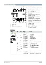
Technical and mechanical design 

The compact build allows for mounting the devices on a standard rail or a wall. 


1

2

3

4

5

6

7

8

9

10

11

12

13

14

15

16

Date/Series
S/N

WLAN
Default

10

11


Service button (network login and WLAN on/off) 

2-port Ethernet switch with 2 LEDs per port for 

display purposes 

Plug-in terminal block with screw terminals  

KNX, PL-link, for future use 

Plug-in terminal block with screw terminals  

Power supply 

Plug-in terminal blocks with screw terminals  

Digital input, for future use 

Plug-in terminal block with screw terminals  

M-bus, for future use 

10  Plug-in terminal block with screw terminals  

COM1 / COM2 (MS/TP or Modbus) 

11  DIP switches for bus termination and polarization 

COM1 / COM2 

12  Slider for mounting on standard mounting rails 
13  Eyelets for cable ties 

Plastic housing 

14  Holes for wall mounting  

Front cover 

15  Date / Series and Serial number 

LEDs for communication and state 

16  QR code for default WLAN access 

Description see Technical data  


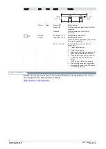
LED displays 


Activity 

LED 

Color 

Activity 

Function 


Ethernet 

1/2 

Green 

Continuously ON 

Continuously OFF 

Flashing 

Link active 

No connection 

Network traffic 

Yellow 

Continuously ON 

Continuously OFF 

Link 100 Mbps 

Link 10 Mbps 

RUN 

Green 

Continuously ON 

Continuously OFF 

Flashing 

Device operational 

Device not operational 

Start-up or program halted 

Red  

Continuously OFF 

Continuously ON 

Rapid flashing 

OK 

HW or SW fault 

Firmware or application missing/corrupted 


Blue 

Continuously ON 

Continuously OFF 

Connection to the cloud OK  

No connection to the cloud 

BAT 

Red 

Continuously OFF 

Continuously ON 

Optional battery OK 

Optional battery empty - replace 

COM… 

Yellow 

Flashing  

Continuously OFF 

Communication 

No communication to subsystem 

KNX 

(for future 

use) 

Yellow 


SVC 

Red 

Continuously OFF 

Flashing 

OK 

Device is not configured 

Flashing per wink 

command 

Identification of the device after receipt of 

wink command 

Содержание Desigo PXC5.E003

Страница 1: ...BACnet MS TP and Modbus devices Communication BACnet IP 2 port Ethernet switch for low cost cabling Integration of Modbus data points via RTU and or TCP Integration of BACnet MS TP devices WLAN interface for engineering and commissioning Operating voltage AC 24 V Mounted on standard rails or on the wall Plug in screw terminal blocks ...

Страница 2: ...et communication on IP or MS TP in compliance with the BACnet standard including B BC profile Rev 1 15 Wireless connection for engineering and commissioning Cloud connectivity for remote access Integration of Modbus data points via RTU and or TCP Type summary Type Order number Description PXC5 E003 S55375 C103 System controller to integrate up to 500 Modbus data points via RTU and or TCP up to 30 ...

Страница 3: ...using 14 Holes for wall mounting 2 Front cover 15 Date Series and Serial number 3 LEDs for communication and state 16 QR code for default WLAN access Description see Technical data LED displays Activity LED Color Activity Function Ethernet 1 2 Green Continuously ON Continuously OFF Flashing Link active No connection Network traffic Yellow Continuously ON Continuously OFF Link 100 Mbps Link 10 Mbps...

Страница 4: ... no client is connected As per description Do the following to reset the device to factory state 1 Power off the device 2 Power on the device 3 Wait until all LEDs light up and turn off again then press the Service button 4 Keep the Service button pressed until all LEDs light up then release the button All LEDs go off the device restarts 5 Wait until the device has fully started unconfigured green...

Страница 5: ... a flat surface Plug in screw terminals connect power and interfaces Ambient temperature 5 50 C 23 122 F Ambient temperature 5 45 C 23 113 F Wall horizontal From left to right From right to left Overhead Wall vertically From top to bottom From bottom to top On a horizontal surface CAUTION Risk of overheating for failure to comply with ambient temperature Burning and damage to the device Ensure suf...

Страница 6: ... GByte RAM 8 GByte eMMC Data backup in the event of power failure Energy reserve Supercap to support real time clock 7 days Energy reserve can be extended to min 1 month using optional battery CR2032 Battery safety requirement and specification for CR2032 according to IEC 60086 4 or UL1642 Battery must be rated for ambient temperature 70 C 158 F Data available if stored to flash memory Occurs ever...

Страница 7: ...hable with DIP switch Internal bus polarization 270 Ohm pull up pull down resistances switchable with DIP switch Cabling in house cabling only Distance between 2 devices Length of the MS TP line 3 wire cable shielded Max 500 m 1650 ft Max 1000 m 3300 ft Protection Short circuit proof Protection against faulty wiring with AC 24 V WLAN interface Interface type Wireless access point Supported standar...

Страница 8: ... UL cUL approbation US Canada UL916 http ul com database CSA certification C22 2 http csagroup org services industries product listing FCC CFR 47 Part 15 Class B BACnet B BC Environmental compatibility 1 The product environmental declaration 1 contains data on environmentally compatible product design and assessments RoHS compliance materials composition packaging environmental benefit disposal 1 ...

Страница 9: ...ion is subject to the following two conditions 1 This device may not cause interference and 2 this device must accept any interference received including interference that may cause undesired operation Radio frequency radiation exposure Information for USA and Canada This equipment complies with FCC and IC radiation exposure limits set forth for an uncontrolled environment This equipment should be...

Страница 10: ...nation Polar On off Switch for polarization 65 66 67 COM1 Interface EIA 485 Modbus MS TP 68 69 70 COM2 71 72 MBUS M bus interface for future use Warranty Technical data on specific applications are valid only together with Siemens products listed under Equipment combinations Siemens rejects any and all warranties in the event that third party products are used ...

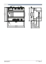
Страница 11: ..._b Smart Infrastructure 2020 07 10 Dimensions All dimensions in mm and inches 124 4 88 117 4 61 110 4 33 129 5 08 4 1 0 1 6 144 5 67 26 5 1 04 45 1 77 65 5 2 58 70 5 2 78 4 0 16 21 5 0 85 11 0 43 45 1 77 21 5 0 85 11 0 43 35 5 1 40 49 1 91 ...

Страница 12: ...itzerland Ltd Smart Infrastructure Global Headquarters Theilerstrasse 1a CH 6300 Zug Tel 41 58 724 2424 www siemens com buildingtechnologies Siemens Switzerland Ltd 2020 Technical specifications and availability subject to change without notice Document ID A6V11646020_en _b Edition 2020 07 10 ...

Отзывы: