37/73
Building Technologies Division
Basic Documentation LME39…
CC1P7106en
11 Inputs and outputs/internal connection diagram/program sequence of LME39.400...
08.12.2017
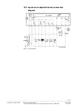
11.2 Inputs and outputs/internal connection
diagram
NT
RESET
EK
FSV
ION
L
N
M
BV1
BV2
Z
AL
P
12
GP
STB
7106a07e/0708
EK2
K1
K2
/1
K2
/2
K3
K4
K5
BCI
H
Si
T
R / W
2
3
10
7
4
5
9
6
11
8
1
CP
I
DB
R2
ZV1
C control
Figure 15: Internal diagram
11.3 Application example
Warning!
The connection diagram shown is merely an example which must be adapted
in the individual case depending on the application!
Note!
In extremely EMC-stressed environments, burners without fan motor or burners
equipped with fan control via auxiliary contactor should use an AGK25 to produce a
burden on terminal 3. If not observed, the burner is not reliably started up
12
2
3
11
6
GP/SB
R/W
L
N
M
AGK25
7106a04/1106
HS
LP
R/W
1)
¹) AGK25 is required only if an
auxiliary relay with a coil
resistance of
50 k
is used
Figure 16: Only for burners with fan control via auxiliary contactor with air pressure switch
Recommendation
:


