


8/73
Building Technologies Division
Basic Documentation LME39…
CC1P7106en
1 Safety notes
03.02.2016
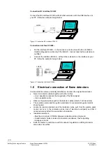
1.4 Installation
notes
Always run the high voltage ignition cables separate from the unit and other cables
while observing the greatest possible distance
Do not mix up live and neutral conductors
Install switches, fuses and earthing, in compliance with local regulations
The connection diagrams show the burner controls with earthed neutral conductor.
In networks with nonearthed neutral conductor and ionization current supervision,
terminal 2 must be connected to the earth conductor via an RC unit (product no.
ARC 4 668 9066 0). It must be made certain that local regulations are complied with
(e.g. protection against electric shock hazard) since AC 120 V (50/60 Hz) or AC 230 V
(50/60 Hz) mains voltage produces peak leakage currents of 2.7 mA
Make certain that the maximum permissible current rating of the connection terminals
will not be exceeded
Do not feed external mains voltage to the control outputs of the unit. When testing the
devices controlled by the burner control (fuel valves, etc.), the burner control must not
be connected
Check the connecting lines of the air pressure switch for short-circuits (air pressure
switch between terminals 2 and 6). If this is not observed, there is a risk of loss of
safety functions
To prevent mixup of different types of burner controls, the LME39... must always be
used in connection with grey plug-in bases AGK11.6. Make absolutely certain that
the live conductor for the control thermostat or pressurestat is tapped after the gas
pressure switch and the safety limit thermostat to be connected to terminal 11 (refer
to Connection diagram)
For safety reasons, feed the neutral conductor to terminal 2. Connect the burner
components (fan, ignition transformer and fuel valves) to the neutral distributor as
shown below in the figure. The connection between neutral conductor and terminal 2
is prewired in the base
Example
Z
M
N
Figure 1: Correct wiring of neutral conductors!
Note!
In extremely EMC-stressed environments, burners without fan motor or burners
equipped with fan control via auxiliary contactor should use an AGK25 to produce a
burden on terminal 3. If not observed, the burner is not reliably started up
Recommendation
:
Legend
V... Fuel
valve
M Fan
motor
Z Ignition
transformer