English
7/1
Siemens plc 1993
7. USING THE SERIAL INTERFACE
7.1 Introduction
The serial interface allows control and/or monitoring of the inverter by a computer system. Using a choice of two
standard serial interface protocols, telegrams consisting of a sequence of data bytes can be sent to the inverter to
instruct it to run, stop, adjust its frequency or adjust any of its parameter values. On receipt of a valid telegram the
inverter sends a response confirming that the requested action has been taken and gives information about its
current operating status. Alternatively, enquiry telegrams can be sent to the inverter to allow values such as
frequency or current to be read back from the inverter. By selecting MONITOR mode, all control commands from
the computer to the inverter will be ignored, but enquiry messages will still be dealt with.
The serial interface operates on a half–duplex basis. This means that it can only respond to messages from the
master controller. It cannot generate unsolicited messages.
The system allows control of up to 31 inverters from one master controller via a 2–wire connection. Each inverter is
allocated a unique address via parameter P21. The master controller can either address each inverter individually
or send broadcast messages which will be acted upon simultaneously by all connected inverters. In the event of a
broadcast message, no reply telegram can be sent because this would result in several inverters trying to transmit
simultaneously via the data bus.
7.2 Hardware Connection
7.2.1 RS485
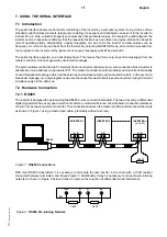
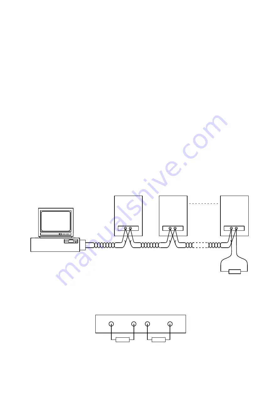
The inverter is designed to operate using the RS485 2–wire connection standard. The two wires carry a differential
digital signal which has a very good rejection of common–mode interference. It is suitable for connection distances
of up to 1 km between master and inverter. The connections between the master and the inverters should be made
as shown in Figure 7 using a twisted pair cable, preferably without a screen.
RS485
+
–
INVERTER 1
A B
X11
INVERTER 2
A B
X11
INVERTER n
A B
X11
(n <= 31)
100
Ω
+
–
+
–
+
–
Figure 7: RS485 Connections
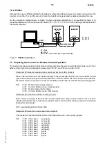
With most RS485 transmitters it is necessary to terminate the last inverter in the chain with a 100
Ω
resistor
connected between terminals A and B
(see Figure 7). Additionally, it may be necessary to connect a pre–biasing
network as shown in Figure 8 below in order to improve the rejection of differential mode interference.
Figure 8: RS485 Pre–biasing Network
+15V
A
B
0V
X11
1 k
Ω
1 k
Ω
Содержание 6SE2101-1AA01
Страница 5: ...English vi Siemens plc 1993 This page intentionally blank ...
Страница 11: ...English 2 2 Siemens plc 1993 This page intentionally blank ...
Страница 53: ...English 7 18 Siemens plc 1993 This page intentionally blank ...
Страница 59: ...Deutsch vi Siemens plc 1993 Diese Seite bleibt absichtlich frei ...
Страница 65: ...Deutsch 2 2 Siemens plc 1993 Diese Seite bleibt absichtlich frei ...
Страница 107: ...Deutsch 7 18 Siemens plc 1993 Diese Seite bleibt absichtlich frei ...

