English
4/3
Siemens plc 1993
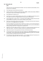
Inverters suitable for use with single phase supplies are fitted with three input terminals (X1.L1, X1.N and X1.
).
Those suitable for use with three phase supplies have four input terminals (X1.L1, X1.L2, X1.L3 and X1.
).
Connect the motor to terminals X1.U, X1.V and X1.W, ensuring that the motor is correctly connected for the
inverter output voltage. For single phase inverters, the motor windings will normally need to be connected in delta
form.
Once the cables have been installed, route them through the rubber cable grommets or, if required, use a
proprietary cable gland.
4.2 Control Connections
Make the control connections to the top board (X11) using shielded cable for analogue signals. After installation,
route the control cable through the right–hand cable grommet or, if required, use a proprietary cable gland.
The control cable should be routed separately from the power supply and motor cables.
The control wires must not run in the same cable duct/trunking as the motor output
cables.
IMPORTANT
Refit the drive’s plastic cover.
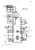
Figure 4 shows an example of an inverter with typical control connections made. Other control configurations are
described in section 5.
Содержание 6SE2101-1AA01
Страница 5: ...English vi Siemens plc 1993 This page intentionally blank ...
Страница 11: ...English 2 2 Siemens plc 1993 This page intentionally blank ...
Страница 53: ...English 7 18 Siemens plc 1993 This page intentionally blank ...
Страница 59: ...Deutsch vi Siemens plc 1993 Diese Seite bleibt absichtlich frei ...
Страница 65: ...Deutsch 2 2 Siemens plc 1993 Diese Seite bleibt absichtlich frei ...
Страница 107: ...Deutsch 7 18 Siemens plc 1993 Diese Seite bleibt absichtlich frei ...


