
instabus EIB
Technical Product Information
September 2001
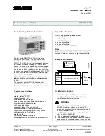
Time Switch 4 Channel REG 372
5WG1 372-5AR01
Mounting and Wiring
General description
The N-system DIN-rail device can be installed to N-
system distribution boards, surface or flush mounted, or
to any available DIN-rail EN 50022-35 x 7,5.
During this the electric connection between the clock
controller and the bus coupling unit is established via
the lateral physical external interface (PEI).
The bus coupling unit is not contained in the volume of
delivery and must be ordered separately.
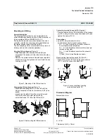
Mounting DIN-rail devices (Figure 2)
-
Slide the device (B1) onto the DIN-rail (B2) and
-
swivel back the device until the slide clicks into place
audibly.
-
Remove the protection film of the adhesive tape (B4),
slip the device to the right and connect it with the bus
coupling unit (B3)
B1
B2
B1
B3
B4
Figure 2: Mounting of the DIN-rail device
Dismounting DIN-rail devices (Figure 3)
-
Slip the bus coupling unit (C1) to the left until the
plug-in connection to the bus terminal unit (C2) is ex-
posed,
-
press down the slide (C4) with a screw-driver and,
click it into place by a slight pressure and
-
swivel the device (C1) from the DIN-rail (C3).
C2
C1
C1
C3
C4
Figure 3: Dismounting the DIN-rail device
Connecting terminal line aerial FA (Figure 4)
-
Remove approx. 5mm of the insulation of the conduc-
tor (D1.1), plug it into the connection blocks (D1) and
tighten the screws (D1.2)
Connections
•
aerial FA: strip insulation for 5mm
permissible conductor types/cross sections:
-
0,5 ... 2,5 mm² single core or flexible conductor,
8 mm ultrasonically compacted
-
0,5 ... 2,5 mm² flexible conductor with terminal pin,
crimped on gas tight
-
0,5 ... 1,5 mm² flexible conductor with connector
sleeve
-
1,0 and 1,5 mm² plain flexible conductor
Disconnecting terminal line aerial FA (figure 3)
-
Detach the screws (E1.2) and plug the conductor
(E1.1) out of the connection block (E1).
D1.1
D1.2
ca. 5 mm
D1
E1.1
E1.2
E1
Figure 4: connecting/disconnecting
terminal lines aerial FA
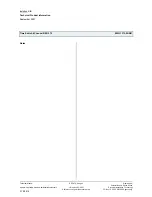
Dimension Diagram
Dimensions in mm
.
9,8
82
45
38
68
b
b = 6 SU
1 Spacer unit (SU) = 18mm
Siemens AG
REG 372, 4 pages
Technical Manual
Automation and Drives Group
Electrical Installation Technology
Siemens AG 2001
Update: http://www.siemens.de/installationstechnik
P.O.Box 10 09 53, D-93009 Regensburg
Subject to change without prior notice
2.18.2.2/3


