instabus EIB
Technical Product Information
September 2001
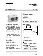
Time Switch 4 Channel REG 372
5WG1 372-5AR01
Technical Specifications
Power supply
Via bus line
Control elements
Keyboard for setting respectively operating the time
switch
Display elements
LCD display unit
Connections
•
10 pin bar (PEI):
for connection with the bus coupling unit
•
aerial FA: length of insulation removal approx. 5 mm
-
0,5 ... 2,5 mm² single core or flexible conductor,
8 mm ultrasonically compacted
-
0,5 ... 2,5 mm² flexible conductor with terminal pin,
crimped on gas tight
-
0,5 ... 1,5 mm² flexible conductor with connector
sleeve
-
1,0 and 1,5 mm² plain flexible conductor
Physical specifications
•
housing: plastic
•
dimensions (W x H x D): 45 x 107 x 68 mm
•
mounting depth: 68 mm
•
distributor section: 46 x 108 mm
•
weight: approx. 175 g
•
installation: rapid mounting on
DIN EN 50022-35 x 7,5 rail
Clock controller
•
response accuracy: usually ±1 s/day at +20°C
•
response margin: 72 h at +20°C
•
duration of charge: 70 h accumulator
•
shortest switching time: 1 s
•
possibility of setting the program: every minute
•
memory locations: 322
•
control selection: yes
•
manual switch: automatic operation/preliminary con-
trol selection FIX ON / FIX OFF
•
switching condition display: yes
•
block establishment: free weekdays and channel
block establishment
•
summer- / wintertime conversion: automatically
•
holiday program: yes
Electrical safety
•
fouling class (according to IEC 664-1): 2
•
protection (according to EN 60529): IP 20
•
protection class (according to IEC 1140): II
•
overvoltage class (according to IEC 664-1): III
•
bus: safety extra low voltage SELV DC 24 V
•
device complies with
EN 50 090-2-2 and IEC 664-1: 1992
Electromagnetic compatibility
complies with
EN 50081-1, EN 50082-2 and EN 50090-2-2
Environmental specifications
•
climatic conditions: EN 50090-2-2
•
ambient temperature operating: - 5 ... + 45
°
C
•
ambient temperature non-op.: - 25 ... + 70
°
C
•
relative humidity (non-condensing): 5 % to 93 %
Certification
EIB certificate
CE norm
complies with the EMC regulations (residential and
functional buildings), and low voltage regulations
Location and Function of the Display and
Operator Elements
Mo
Tu We Th
Fr
Sa
Su
Reset
S/W
Prior. Year
CL
R
1x
N
1
2
3
4
S
Month
h-
m-
h+
m+
Day
I/O
I/O
I/O
I/O
1
2
3
4
A1
A2
A3
A4
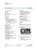
Figure 1: Location of the display and operator elements
A1 terminal connection blocks aerial FA
A2 Keyboard for setting respectively operating the
clock controller
A3 LCD display unit
A4 Physical external interface (PEI) for connection
with the bus coupling unit REG
Technical Manual
REG 372, 4 pages
Siemens AG
Automation and Drives Group
Update: http://www.siemens.de/installationstechnik
Siemens AG 2001
Electrical Installation Technology
Subject to change without prior notice
P.O.Box 10 09 53, D-93009 Regensburg
2.18.2.2/2


