background image


Technical Data and Speed-Torque Diagrams 
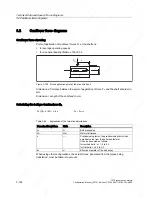
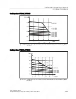
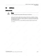
 

3.3 Axial forces 

3.3 

Axial forces 

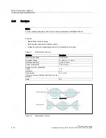
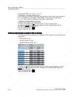
Axial force stressing 


Warning 
Motors with integrated holding brake cannot be subject to axial forces! 


When using, for example, helical toothed wheels as drive element, in addition to the radial 

force, there is also an axial force on the motor bearings. For axial forces, the spring-loading 

of the bearings can be overcome so that the rotor moves corresponding to the axial bearing 

play present (up to 0.2 mm). 
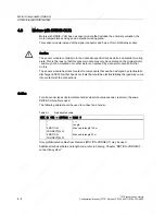
The permissible axial force can be approximately calculated using the following formula: 
F

A

 = 0.35 • F

Q


1FT6 synchronous motors 
Configuration Manual, (PFT6), Edition 12.2004, 6SN1197-0AD12-0BP0 

3-133


Содержание 1FT6031-4AK71-4AH0-Z

Страница 1: ...ÓŁKA JAWNA Jana Dlugosza 2 6 Street 51 162 Wrocław Poland biuro rgbelektronika pl 48 71 325 15 05 www rgbautomatyka pl www rgbelektronika pl DATASHEET www rgbautomatyka pl www rgbelektronika pl OTHER SYMBOLS 1FT6031 4AK71 4AH0 Z SIEMENS ...

Страница 2: ...ed with a wide variety of tools and having several testing stands at their disposal are a guarantee of the highest quality service OUR SERVICES ENCODERS SERVO DRIVERS LINEAR ENCODERS SERVO AMPLIFIERS CNC MACHINES MOTORS POWER SUPPLIERS OPERATOR PANELS CNC CONTROLS INDUSTRIAL COMPUTERS PLC SYSTEMS Repair this product with RGB ELEKTRONIKA ORDER A DIAGNOSIS Buy this product at RGB AUTOMATYKA BUY ...

Страница 3: ... VLQDPLFV RQILJXUDWLRQ 0DQXDO GLWLRQ 6 QFKURQRXV 6HUYRPRWRUV 7 ...

Страница 4: ......

Страница 5: ...on 1 Electrical Connections 2 Technical Data and Speed Torque Diagrams 3 Motor Components Options 4 Dimension Drawings 5 Appendix A SINAMICS 1FT6 Synchronous Motors Configuration Manual PFT6 Edition 12 2004 6SN1197 0AD12 0BP0 ...

Страница 6: ... defined as persons who are authorized to commission ground and label devices systems and circuits in accordance with established safety practices and standards Prescribed Usage Note the following Warning This device may only be used for the applications described in the catalog or the technical description and only in connection with devices or components from other manufacturers which have been ...

Страница 7: ... violate the rights of the registered holder Further information is available on the Internet under http www siemens com motioncontrol This publication was produced with SIPS Siemens AG 2004 All rights reserved The control system may support functions that are not described in this documentation However no claim can be made regarding the availability of these functions when the equipment is first ...

Страница 8: ......

Страница 9: ...the contents of this document are neither part of nor modify any prior or existing agreement commitment or contractual relationship The sales contract contains the entire obligations of Siemens The warranty contained in the contract between the parties is the sole warranty of Siemens Any statements contained herein neither create new warranties nor modify the existing warranty Structure of the doc...

Страница 10: ...23 http www siemens de automation support request If you have any questions regarding the documentation suggestions corrections then please send a fax to the following number 49 9131 98 2176 Fax form Refer to the response sheet at the end of the document 1FT6 synchronous motors iv Configuration Manual PFT6 Edition 12 2004 6SN1197 0AD12 0BP0 ...

Страница 11: ...d hazardous axis movements can occur All of the work carried out on the electrical machine or system must be carried out with it in a no voltage condition SINAMICS drive units are designed for operation on low ohmic grounded line supply systems TN line supply systems Warning The successful and safe operation of this equipment and motors is dependent on professional transport storage installation a...

Страница 12: ...me into contact with the connections Caution SINAMICS drive units with synchronous motors are subject as part of the routine test to a voltage test in accordance with EN 50178 While the electrical equipment of industrial machines is being subject to a voltage test in accordance with EN60204 1 Section 19 4 all SINAMICS drive unit connections must be disconnected withdrawn in order to avoid damaging...

Страница 13: ...contact with plastics and articles of clothing manufactured from man made fibers Electronic boards may only be placed on conductive surfaces table with ESDS surface conductive ESDS foam rubber ESDS packing bag ESDS transport containers Electronic boards may not be brought close to data terminals monitors or television sets Minimum clearance to screens 10 cm Measurements may only be carried out on ...

Страница 14: ...Foreword 1FT6 synchronous motors viii Configuration Manual PFT6 Edition 12 2004 6SN1197 0AD12 0BP0 ...

Страница 15: ... 2 Power connection 2 2 2 2 1 Possible connections 2 2 2 2 2 Connector connection 2 2 2 2 3 Connection through a terminal box 2 3 2 3 DRIVE CLiQ 2 5 2 4 Motors with DRIVE CLiQ 2 5 2 5 Motors without DRIVE CLiQ 2 6 2 6 Rotating the connector at the motor 2 7 3 Technical Data and Speed Torque Diagrams 3 1 3 1 Speed torque diagrams 3 1 3 1 1 Introduction 3 1 3 1 2 1FT6 series non ventilated 3 2 3 1 3...

Страница 16: ...ction 4 13 4 6 2 Planetary gearbox 1 stage 4 13 4 6 3 Planetary gearbox 2 stage 4 18 5 Dimension Drawings 5 1 5 1 Introduction 5 1 5 2 1FT6 with DRIVE CLiQ 5 2 5 2 1 Non ventilated 1FT6 motors 5 2 5 2 2 Force ventilated 1FT6 motors 5 10 5 2 3 Water cooled 1FT6 motors 5 13 5 3 1FT6 without DRIVE CLiQ 5 18 5 3 1 Non ventilated 1FT6 motors 5 18 5 3 2 Force ventilated 1FT6 motors 5 28 5 3 3 Water cool...

Страница 17: ...owers to be dissipated 1 26 Table 1 13 Assignment of the drive out couplings to the motors 1 28 Table 2 1 Description of the diagram 2 4 Table 2 2 Connections for the terminal box 2 4 Table 3 1 1FT6021 non ventilated 3 2 Table 3 2 1FT6024 non ventilated 3 4 Table 3 3 1FT6031 non ventilated 3 6 Table 3 4 1FT6034 non ventilated 3 8 Table 3 5 1FT6041 non ventilated 3 10 Table 3 6 1FT6044 non ventilat...

Страница 18: ... 38 1FT6108 force ventilated 3 76 Table 3 39 1FT6132 force ventilated 3 78 Table 3 40 1FT6132 force ventilated 3 80 Table 3 41 1FT6134 force ventilated 3 82 Table 3 42 1FT6134 force ventilated 3 84 Table 3 43 1FT6136 force ventilated 3 86 Table 3 44 1FT6136 force ventilated 3 88 Table 3 45 1FT6163 force ventilated 3 90 Table 3 46 1FT6168 force ventilated 3 92 Table 3 47 1FT6062 water cooled 3 94 T...

Страница 19: ... 6 Table 4 6 Prefabricated cable 4 6 Table 4 7 Technical data absolute value encoder 4 7 Table 4 8 Prefabricated cable 4 9 Table 4 9 Technical data resolvers 4 10 Table 4 10 Connection assignment for 12 pin flange mounted socket 4 11 Table 4 11 Prefabricated cable 4 11 Table 4 12 Technical data of the holding brakes used for 1FT6 motors 4 12 Table 4 13 1FT6 series with 1 stage planetary gearbox al...

Страница 20: ...Table of Contents 1FT6 synchronous motors xiv Configuration Manual PFT6 Edition 12 2004 6SN1197 0AD12 0BP0 ...

Страница 21: ...mance speed setting range and rotational and positioning accuracy The motors are primarily designed for operation without external cooling and the heat is dissipated through the motor surface The heat that is predominantly generated in the stator winding and in the stator core can be directly dissipated via the good thermal coupling to the special merits here motor enclosure The concept of brushle...

Страница 22: ...se in very dirty environments Simple installation due to reduced cabling requirements Can absorb high cantilever forces Application High performance machine tools Machines with high requirements in terms of dynamic performance and precision Standards regulations The appropriate standards regulations are directly assigned to the functional requirements 1FT6 synchronous motors 1 2 Configuration Manu...

Страница 23: ...B A ooled approx 70 dB A SH 132 to 160 force ventilated approx 74 dB A N Bearings Roller bearings with permanent grease lubrication lubrication over the bearing lifetime bearing lifetime 20000 h SH 36 48 Locating bearings on the NDE Winding insulation acc to EN 60034 1 IEC 60034 1 Temperature class F for a winding temperature rise of ΔT 100 K at an ambient temperature of 40 C Installation altitude...

Страница 24: ...f 90 H half key balancing 1 When using an absolute value encoder and non ventilated or forced ventilation the rated torque is reduced by 10 refer to the Table Technical data 2 Power de rating for temperatures 40 C and or installation altitudes 1000 m refer to the Configuration Manual General Section for Synchronous Motors 3 Forced ventilation cannot be used in the presence of flammable corrosive e...

Страница 25: ...HQG 5DGLDO HFFHQWULFLW ROGLQJ EUDNH 9LEUDWLRQ VHYHULW OHYHO HJUHH RI SURWHFWLRQ QFRGHU V VWHP ZLWK ILWWHG NH 1 ZLWKRXW ZLWK ILWWHG NH 1 ZLWK ZLWK ILWWHG NH 5 ZLWKRXW ZLWK ILWWHG NH 5 ZLWK VPRRWK VKDIW 1 ZLWKRXW VPRRWK VKDIW 1 ZLWK VPRRWK VKDIW 5 ZLWKRXW VPRRWK VKDIW 5 ZLWK 1 3 1 3 1 3 1 3 5 3 5 3 5 3 5 3 1 Only for SH 63 80 100 2 Not for force ventilated motors 3 For 1FT6062 only in conjunction wi...

Страница 26: ...HUYRPRWRU 6HULHV UDPH VL H HQJWK RGLQJ FRUH W SH 5DWHG VSHHG 530 530 530 530 RQQHFWRU RXWOHW GLUHFWLRQ WUDQVYHUVH ULJKW QRW IRU 6 WUDQVYHUVH OHIW QRW IRU 6 D LDO 1 D LDO ZLWKRXW KROGLQJ EUDNH ZLWK KROGLQJ EUDNH 7 QFRGHU V VWHP 1FT6 synchronous motors 1 6 Configuration Manual PFT6 Edition 12 2004 6SN1197 0AD12 0BP0 ...

Страница 27: ...J 5DWHG VSHHG 530 530 7 SH RI FRQVWUXFWLRQ 0 7 QFRGHU V VWHP 6K DIW HQG 6KDIW HQG ZLWK NH 7ROHUDQFH 1 ZLWKRXW EUDNH VPRRWK VKDIW HQG WROHUDQFH 1 ZLWKRXW EUDNH VPRRWK VKDIW HQG WROHUDQFH 5 ZLWKRXW EUDNH 9LEUDWLRQ VHYHULW OHYHO DQG GHJUHH RI SURWHFWLRQ 9LEUDWLRQ VHYHULW OHYHO 1 9LEUDWLRQ VHYHULW OHYHO 1 9LEUDWLRQ VHYHULW OHYHO 5 9LEUDWLRQ VHYHULW OHYHO 5 3 3 3 3 3ROH QXPEHU 6KDIW HQG ZLWK NH 7ROHUDQ...

Страница 28: ...QWLODWHG ದ 6 ದ JN ದ 6 ದ JN ದ 6 ದ JN ದ 6 ದ JN ದ 6 ದ JN ದ 6 ದ JN RUFHG YHQWLODWLRQ ದ 6 6 ದ JN ದ 6 6 ದ JN ದ 6 6 ದ JN ದ 6 6 ದ JN ದ 6 6 ದ JN ದ 6 JN ದ 6 JN DWHU FRROLQJ ದ 6 ದ JN ದ JN ದ JN ದ JN ದ JN ದ JN ದ JN 3ROH QXPEHU ZLWKRXW EUDNH FDEOH ZLWK RYHUDOO VKLHOG ZLWK EUDNH FDEOH ZLWK RYHUDOO VKLHOG HQJWKV P H DPSOHV P P P P DEOHV DUH QRW LQFOXGHG ZLWK WKH PRWRUV WKH PXVW EH VHSDUDWHO RUGHUHG 1FT6 synchrono...

Страница 29: ...Chapter Connection system MOTION CONNECT 6FX5002 MOTION CONNECT 500 TION CONNECT 7 Cables can be supplied in integer lengths of precisely 1 meter Length code refer to the Configuration Manual General Part for Synchronous Motors 8 For 1FT613 motors the maximum current and the rated current of the converter must be carefully observed 1FT616 motors can only be operated with SIMOVERT MASTERDRIVES MC d...

Страница 30: ...ncoder due to the max temperature of the encoder 2 Power connector and terminal box mutually exclude one another 3 Motor with terminal boxes max cross section that can be connected refer to the Table Connections for terminal boxes ends on the size of the selected power module refer to the Configuration Manual Drive Converters 5 Motor with terminal boxes power and signals cables refer to Catalog Ch...

Страница 31: ...ze of the selected power module refer to the Configuration Manual Drive Converters 5 Motor with terminal boxes power and signals cables refer to Catalog Chapter Connection system MOTION CONNECT 6FX5002 MOTION CONNECT 500 TION CONNECT 7 Cables can be supplied in integer lengths of precisely 1 meter Length code refer to the Configuration Manual General Part for Synchronous Motors 8 For 1FT613 motors...

Страница 32: ...YHUDOO VKLHOG ZLWK EUDNH FDEOH ZLWK RYHUDOO VKLHOG HQJWKV P H DPSOHV P P P P DEOHV DUH QRW LQFOXGHG ZLWK WKH PRWRUV WKH PXVW EH VHSDUDWHO RUGHUHG RRWQRWHV UHIHU WR WKH QH W SDJH Q1 530 0 1P 01 1P 01 1P 0RWRU W SH 7 ದ 1 RQQHFWRU URVV VHFWLRQ PP DEOH W SH ದ 7HUPLQDO ER 1RQ YHQWLODWHG ದ ჰ 6 ದ ದ ჰ ჰ 6 ದ ದ ჰ 6 ದ ದჰ ჰ 6 ದ ದჰ ჰ 6 ದ ದ ჰ 6 ದ ದჰ ჰ 6 ದ ದ ჰ ჰ 6 ದ ದ ჰ ჰ 6 ದ ದ ჰ 6 ದ JN ದ ჰ 6 ದ JN ದ ჰ 6 ದ JN ದ ჰ...

Страница 33: ...2 Power connector and terminal box mutually exclude one another 3 Motor with terminal boxes max cross section that can be connected refer to the Table Connections for terminal boxes ends on the size of the selected power module refer to the Configuration Manual Drive Converters 5 Motor with terminal boxes power and signals cables refer to Catalog Chapter Connection system MOTION CONNECT 6FX5002 MO...

Страница 34: ... 2 Power connector and terminal box mutually exclude one another 3 Motor with terminal boxes max cross section that can be connected refer to the Table Connections for terminal boxes ends on the size of the selected power module refer to the Configuration Manual Drive Converters 5 Motor with terminal boxes power and signals cables refer to Catalog Chapter Connection system MOTION CONNECT 6FX5002 M...

Страница 35: ...to account here Higher currents and torques can occur than those calculated as a result of the saturation The ratings of the resistors must match the particular I2t load capability refer to the Configuration Manual General Section for Synchronous Motors Non ventilated Table 1 3 Resistor braking for the 1FT6 series shaft heights 28 to 48 non ventilated Average braking torque Mbr rms Nm rms braking ...

Страница 36: ... 7 7 0 9 0 8 1 1FT6062 6AH7 5 5 3 2 5 7 7 0 13 11 1FT6062 6AK7 4 4 2 6 5 7 7 0 17 15 1FT6064 6AC7 5 9 6 8 9 1 11 9 3 8 5 1FT6064 6AF7 5 0 5 5 9 1 11 14 12 1FT6064 6AH7 3 6 4 4 9 1 11 20 18 1FT6064 6AK7 2 9 3 6 9 1 11 27 24 SH 80 non ventilated 1FT6081 8AC7 6 5 5 1 6 9 8 6 7 8 7 1 1FT6081 8AF7 5 1 4 1 6 9 8 6 12 11 1FT6081 8AH7 3 7 3 2 6 9 8 6 18 16 1FT6081 8AK7 3 4 2 4 6 9 8 6 21 19 1FT6082 8AC7 4...

Страница 37: ...5 24 30 51 46 1FT6105 8AB7 2 2 21 43 54 33 29 1FT6105 8AC7 1 7 17 43 54 44 39 1FT6105 8AF7 1 2 13 43 54 65 58 1FT6108 8AB7 1 4 32 71 88 53 47 1FT6108 8AC7 1 2 26 71 88 68 61 1FT6108 8AF7 0 9 21 71 88 99 89 SH 132 non ventilated 1FT6132 6AB7 1 0 1 37 83 105 56 50 1FT6132 6AC7 1 2 1 32 83 105 75 67 1FT6132 6AF7 0 8 1 23 83 105 110 100 1FT6134 6AB7 1 2 1 47 110 140 72 65 1FT6134 6AC7 0 9 1 40 110 140...

Страница 38: ... 1FT6108 8SC7 0 9 27 71 88 77 69 1FT6108 8SF7 0 6 20 71 88 115 103 SH 132 force ventilated 1FT6132 6SB7 1 2 36 1 83 105 63 57 1FT6132 6SC7 1 0 30 1 83 105 83 74 1FT6132 6SF7 0 7 23 1 83 105 120 110 1FT6134 6SB7 0 9 49 1 110 140 81 73 1FT6134 6SC7 0 8 40 1 110 140 105 95 1FT6134 6SF7 0 6 30 1 110 140 150 140 1FT6136 6SB7 0 8 54 1 130 170 99 88 1FT6136 6SC7 0 6 43 1 130 170 130 120 1FT6136 6SF7 0 5 ...

Страница 39: ... 26 1FT6084 8WH7 1 6 6 5 18 22 44 40 1FT6084 8WK7 1 4 4 7 18 22 54 48 1FT6086 8WF7 1 6 11 27 34 42 38 1FT6086 8WH7 1 1 7 5 27 34 61 55 1FT6086 8WK7 1 1 6 6 27 34 74 66 SH 100 water cooling 1FT6105 WC7 0 8 17 44 55 65 58 1FT6105 WF7 0 6 14 44 55 96 86 1FT6108 WB7 1 2 33 71 88 58 52 1FT6108 WC7 0 9 27 71 88 77 69 1FT6108 WF7 0 6 21 71 88 115 103 SH 132 water cooling 1FT6132 6WB7 0 9 40 1 85 105 72 6...

Страница 40: ... according to M0 60 K the additional braking resistor is not required 2 It is absolutely prohibited to short circuit the winding when using smaller supplementary resistors than those specified When braking from the rated speed the resistors listed prevent partial de magnetization of the rotor 1FT6 synchronous motors 1 20 Configuration Manual PFT6 Edition 12 2004 6SN1197 0AD12 0BP0 ...

Страница 41: ...s reversed this reduces the torque Mechanical changes to the motor with respect to non ventilated versions The power connector is about 12 mm higher A sheet metal envelope is located over the motor frame from the non drive end side The axial fan is mounted in this sheet metal envelope There is a cut out in the sheet metal envelope at the connector positions This means that the motor is only partia...

Страница 42: ...h the enclosure corners of the extruded p Connection via terminal box Supply voltage 3 ph 400 480 V AC 50 60 Hz Maximum current 0 8 A Minimum clearance between parts and components mounted by the customer and the air discharge opening The following minimum clearance must be maintained between parts and components mounted by the customer and the air discharge opening Table 1 8 Minimum clearance to ...

Страница 43: ... to retrofit a motor for water cooling The cooling medium must be pre cleaned and filtered in order to prevent the cooling circuit from becoming blocked The maximum permissible particle size after filtering is 100 mm Cooling circuit Notice If current is flowing through the motor then the cooling circuit must be activated Table 1 9 Technical data for the cooling circuit Motor type Water flow rate l...

Страница 44: ... corrosion agent and the cooling system We recommend that an anti corrosion agent is added to water as cooling medium e g Antifrogen N from the Hoechst Company or Tyfocor from Tyforop Chemie GmbH refer to the Table below Observe the specifications of the anti corrosion agent manufacturer regarding the ratio of water to anti corrosion agent For Tyfocor the ratio of 75 water and 25 anti corrosion ag...

Страница 45: ...52076 Aachen Phone 02408 14060 Schilling Chemie GmbH u Produktions KG Steinbeißstr 20 D 71691 Freiberg Phone 07141 7030 Note These recommendations involve third party products which we know to be basically suitable It goes without saying that similar products from other manufacturers can also be used Our recommendations should be considered as such We cannot accept any liability for the quality an...

Страница 46: ...00 1FT6064 6WH7 850 1FT6064 6WK7 900 1FT6084 8WF7 1500 1FT6084 8WH7 1900 1FT6084 8WK7 2200 1FT6086 8WF7 1800 1FT6086 8WH7 2000 1FT6086 8WK7 2400 1FT6105 8WC7 2000 1FT6105 8WF7 2100 1FT6108 8WB7 1900 1FT6108 8WC7 2100 1FT6108 8WF7 2100 1FT6132 6WB7 2600 1FT6132 6WD7 2700 1FT6134 6WB7 2700 1FT6134 6WD7 3100 1FT6136 6WB7 3300 1FT6136 6WD7 3600 1FT6138 6WB7 3600 1FT6138 6WD7 4000 1FT6163 8WB7 4500 1FT...

Страница 47: ...cturer refer to the Catalog The cooling power is calculated from the sum of the power losses of the connected motors The power of the pump and the distribution to different cooling circuits should be engineered corresponding to the specified flow and the pressure losses of the individual cooling circuits If one pump is used with distribution to several cooling circuits then it may be necessary to ...

Страница 48: ... 25 8 1 1FT6041 19 19 17 34 32 1FT6044 19 24 60 120 39 1FT606x 6A 24 24 60 120 43 1FT6062 6W 24 24 60 120 43 1FT6064 6W 24 28 60 120 91 1FT608x 8A 32 28 160 320 102 1FT608x 8S 32 28 160 320 102 1FT6084 8W 32 28 160 320 102 1FT6086 8W 32 38 325 650 113 1FT6102 5 38 38 325 650 122 1FT6108 38 42 450 900 1FT613x 6A 48 42 450 900 1FT613x 6S 48 42 450 900 1FT6132 4 6W 48 48 525 1050 1FT6136 8 6W 48 55 6...

Страница 49: ...Electrical Connections 2 2 1 Connection overview Figure 2 1 Connection overview SINAMICS S120 1FT6 synchronous motors Configuration Manual PFT6 Edition 12 2004 6SN1197 0AD12 0BP0 2 1 ...

Страница 50: ... either be connected via power connectors or via terminal boxes Several motors types can only be connected through a power connector 2 2 2 Connector connection Connection assignment power connector at the motor UDNH FRQQHFWLRQ 5 5ದ RQO ZKHQ RUGHUHG 8 9 DEOH FRQQHFWLRQ 8 9 8 9 5 5 ದ 5 ದ 5 1 ದ 1 RQQHFWRU VL H DQG RQQHFWRU VL H Figure 2 2 Power connection 1FT6 synchronous motors 2 2 Configuration Man...

Страница 51: ... must be connected Cable lugs acc to DIN 46234 must be used Connect up an optional brake refer to the diagram Notice Motors with a rated power of more than 100 kW must be grounded using the additional M12 grounding stud provided at the NDE bearing endshield Figure 2 3 Terminal assignment in the terminal boxes 1FT6 synchronous motors Configuration Manual PFT6 Edition 12 2004 6SN1197 0AD12 0BP0 2 3 ...

Страница 52: ...cross section per phase Ground connection Brake connection 2 gk130 1 x Pg29 30 36 3 x M4 1 x 6 mm2 M4 1 5 mm2 gk230 1 x Pg29 30 66 3 x M5 1 x 16 mm2 M4 1 5 mm2 gk420 1 x Pg36 37 104 4 x M10 1 x 35 mm2 M6 1 5 mm2 gk630 2 x M32 x 1 5 25 112 3 x M10 2 x 16 mm2 M10 gk630 2 x M40 x 1 5 32 176 3 x M10 2 x 35 mm2 M10 gk630 2 x M50 x 1 5 41 209 3 x M10 2 x 50 mm2 M10 1 Data acc to DIN EN 60204 1 routing t...

Страница 53: ...well as an electronic rating plate with a unique identification number and motor and encoder specific data These motors with DRIVE CLiQ can be connected to the corresponding motor module directly via the MOTION CONNECT DRIVE CLiQ cables supplied This means that data is directly transferred to the control unit These motors make start up and diagnostics much easier as the motor and encoder type can ...

Страница 54: ...convert them to DRIVE CLiQ In conjunction with motor encoders the motor temperature can also be evaluated using sensor modules Additional information is provided in the SINAMICS Equipment Manual 6LJQDO FDEOH 3RZHU FDEOH 6 1 0 6 6 0 5 9 L4 6HQVRU 0RGXOH DELQHW RQQHFWLQJ WKH HQFRGHU WKURXJK WKH 6HQVRU 0RGXOH DELQHW 0RWRU a 0RWRU 0RGXOHV Figure 2 5 Connecting encoders without DRIVE CLiQ 1FT6 synchron...

Страница 55: ...d stop The connector should be rotated using a mating connector attached at the connector thread Connecting cables must be secured against tensile stress and bending The motors connectors must be secured so that they cannot be rotated any further It is not permissible to subject connectors to a continuous force In order to guarantee the degree of protection the connector m 7 ჰ 7 ჰ FRQQHFWRUV FDQQR...

Страница 56: ...Electrical Connections 2 6 Rotating the connector at the motor 1FT6 synchronous motors 2 8 Configuration Manual PFT6 Edition 12 2004 6SN1197 0AD12 0BP0 ...

Страница 57: ...for Synchronous Motors for a description of how the voltage limiting characteristics are shifted The specified thermal S3 limit characteristics are referred to ΔT 100 K for 1 min cycle duration for SH 28 10 min cycle duration for SH 36 48 63 80 100 132 160 1FT6 synchronous motors Configuration Manual PFT6 Edition 12 2004 6SN1197 0AD12 0BP0 3 1 ...

Страница 58: ... kgm2 6000 6 0 3 1 1 0 33 0 40 1 0 1 25 0 28 0 21 Optimum operating point Optimum speed Optimum power nopt Popt RPM kW 6000 0 19 Limiting data Max permissible speed mech Max torque Max current nmax Mmax Imax RPM Nm A 12000 1 5 5 Physical constants Torque constant Voltage constant Rotating field inductance Electrical time constant Shaft torsional stiffness Mechanical time constant Weight with brake...

Страница 59: ...HULVWLFV D E OLH RXWVLGH WKH PD SHUPLVVLEOH VSHHG UDQJH 6SHHG 530 Figure 3 1 Speed torque diagram 1FT6021 6AK71 a SINAMICS S120 SMART LINE VDC link 540V DC Vmot 380Vrms b SINAMICS S120 ACTIVE LINE VDC link 600V DC Vmot 425Vrms 1FT6 synchronous motors Configuration Manual PFT6 Edition 12 2004 6SN1197 0AD12 0BP0 3 3 ...

Страница 60: ... 0 9 0 66 0 8 1 0 1 25 0 41 0 34 Optimum operating point Optimum speed Optimum power nopt Popt RPM kW 6000 0 31 Limiting data Max permissible speed mech Max torque Max current nmax Mmax Imax RPM Nm A 12000 3 15 5 Physical constants Torque constant Voltage constant Rotating field inductance Electrical time constant Shaft torsional stiffness Mechanical time constant Weight with brake Weight without ...

Страница 61: ... 6 6 6 PLQ 6 PLQ 6 PLQ 6SHHG 530 Figure 3 2 Speed torque diagram 1FT6024 6AK71 a SINAMICS S120 SMART LINE VDC link 540V DC Vmot 380Vrms b SINAMICS S120 ACTIVE LINE VDC link 600V DC Vmot 425Vrms 1FT6 synchronous motors Configuration Manual PFT6 Edition 12 2004 6SN1197 0AD12 0BP0 3 5 ...

Страница 62: ... Optimum speed Optimum power nopt Popt RPM kW 6000 0 47 Limiting data Max permissible speed mech Max torque Max current nmax Mmax Imax RPM Nm A 9700 4 5 8 Physical constants Torque constant Voltage constant Rotating field inductance Electrical time constant Shaft torsional stiffness Mechanical time constant Weight with brake Weight without brake kT kE Rph LD Tel ct Tmech Tth m m Nm A V 1000 RPM Oh...

Страница 63: ...ta and Speed Torque Diagrams 3 1 Speed torque diagrams 6 6 6 6 6 D E Q 530 0 1P Figure 3 3 Speed torque diagram 1FT6031 4AK71 1FT6 synchronous motors Configuration Manual PFT6 Edition 12 2004 6SN1197 0AD12 0BP0 3 7 ...

Страница 64: ... 4 2 1 1 65 2 2 1 2 6 1 22 1 1 Optimum operating point Optimum speed Optimum power nopt Popt RPM kW 6000 0 88 Limiting data Max permissible speed mech Max torque Max current nmax Mmax Imax RPM Nm A 9700 7 7 10 5 Physical constants Torque constant Voltage constant Rotating field inductance Electrical time constant Shaft torsional stiffness Mechanical time constant Weight with brake Weight without b...

Страница 65: ...6 6 6 6 6 D E Q 530 0 1P Figure 3 4 Speed torque diagram 1FT6034 a SINAMICS S120 SMART LINE VDC link 540V DC Vmot 380Vrms b SINAMICS S120 ACTIVE LINE VDC link 600V DC Vmot 425Vrms 1FT6 synchronous motors Configuration Manual PFT6 Edition 12 2004 6SN1197 0AD12 0BP0 3 9 ...

Страница 66: ... 2 15 2 6 2 5 3 0 3 98 2 9 Optimum operating point Optimum speed Optimum power nopt Popt RPM kW 3000 0 68 6000 1 07 Limiting data Max permissible speed mech Max torque Max current nmax Mmax Imax RPM Nm A 7700 10 7 7 7700 10 12 8 Physical constants Torque constant Voltage constant Rotating field inductance Electrical time constant Shaft torsional stiffness Mechanical time constant Weight with brake...

Страница 67: ...ed torque diagram 1FT6041 4AF71 6 6 6 6 6 D E Q 530 0 1P Figure 3 6 Speed torque diagram 1FT6041 4AK71 a SINAMICS S120 SMART LINE VDC link 540V DC Vmot 380Vrms b SINAMICS S120 ACTIVE LINE VDC link 600V DC Vmot 425Vrms 1FT6 synchronous motors Configuration Manual PFT6 Edition 12 2004 6SN1197 0AD12 0BP0 3 11 ...

Страница 68: ... 5 0 4 8 5 9 6 18 5 1 Optimum operating point Optimum speed Optimum power nopt Popt RPM kW 3000 1 35 6000 1 88 Limiting data Max permissible speed mech Max torque Max current nmax Mmax Imax RPM Nm A 7700 18 11 7700 18 22 Physical constants Torque constant Voltage constant Rotating field inductance Electrical time constant Shaft torsional stiffness Mechanical time constant Weight with brake Weight ...

Страница 69: ...eed torque diagram 1FT6044 AF71 6 6 6 6 6 D E Q 530 0 1P Figure 3 8 Speed torque diagram 1FT6044 4AK71 a SINAMICS S120 SMART LINE VDC link 540V DC Vmot 380Vrms b SINAMICS S120 ACTIVE LINE VDC link 600V DC Vmot 425Vrms 1FT6 synchronous motors Configuration Manual PFT6 Edition 12 2004 6SN1197 0AD12 0BP0 3 13 ...

Страница 70: ...3 3 4 0 2 2 2 7 9 3 6 Optimum operating point Optimum speed Optimum power nopt Popt RPM kW 2000 0 77 3000 1 1 Limiting data Max permissible speed mech Max torque Max current nmax Mmax Imax RPM Nm A 9100 16 14 Physical constants Torque constant Voltage constant Rotating field inductance Electrical time constant Shaft torsional stiffness Mechanical time constant Weight with brake Weight without brak...

Страница 71: ...eed torque diagram 1FT6061 6AC7 6 6 6 6 6 D E Q 530 0 1P Figure 3 10 Speed torque diagram 1FT6061 6AF7 a SINAMICS S120 SMART LINE VDC link 540V DC Vmot 380Vrms b SINAMICS S120 ACTIVE LINE VDC link 600V DC Vmot 425Vrms 1FT6 synchronous motors Configuration Manual PFT6 Edition 12 2004 6SN1197 0AD12 0BP0 3 15 ...

Страница 72: ... 3 3 4 4 5 9 3 6 Optimum operating point Optimum speed Optimum power nopt Popt RPM kW 4500 1 37 5000 1 38 Limiting data Max permissible speed mech Max torque Max current nmax Mmax Imax RPM Nm A 9100 16 21 9100 16 26 Physical constants Torque constant Voltage constant Rotating field inductance Electrical time constant Shaft torsional stiffness Mechanical time constant Weight with brake Weight witho...

Страница 73: ...eed torque diagram 1FT6061 6AH7 6 6 6 6 6 D E Q 530 0 1P Figure 3 12 Speed torque diagram 1FT6061 6AK7 a SINAMICS S120 SMART LINE VDC link 540V DC Vmot 380Vrms b SINAMICS S120 ACTIVE LINE VDC link 600V DC Vmot 425Vrms 1FT6 synchronous motors Configuration Manual PFT6 Edition 12 2004 6SN1197 0AD12 0BP0 3 17 ...

Страница 74: ... 6 3 3 4 1 11 8 8 5 Optimum operating point Optimum speed Optimum power nopt Popt RPM kW 2000 1 09 3000 1 48 Limiting data Max permissible speed mech Max torque Max current nmax Mmax Imax RPM Nm A 9100 24 15 9100 24 22 Physical constants Torque constant Voltage constant Rotating field inductance Electrical time constant Shaft torsional stiffness Mechanical time constant Weight with brake Weight wi...

Страница 75: ...eed torque diagram 1FT6062 6AC7 6 6 6 6 6 D E Q 530 0 1P Figure 3 14 Speed torque diagram 1FT6062 6AF7 a SINAMICS S120 SMART LINE VDC link 540V DC Vmot 380Vrms b SINAMICS S120 ACTIVE LINE VDC link 600V DC Vmot 425Vrms 1FT6 synchronous motors Configuration Manual PFT6 Edition 12 2004 6SN1197 0AD12 0BP0 3 19 ...

Страница 76: ...6 6 2 7 6 11 8 8 5 Optimum operating point Optimum speed Optimum power nopt Popt RPM kW 4500 1 70 4500 1 70 Limiting data Max permissible speed mech Max torque Max current nmax Mmax Imax RPM Nm A 9100 24 31 9100 24 41 Physical constants Torque constant Voltage constant Rotating field inductance Electrical time constant Shaft torsional stiffness Mechanical time constant Weight with brake Weight wit...

Страница 77: ...eed torque diagram 1FT6062 6AH7 6 6 6 ದ 6 ದ 6 ದ D E Q 530 0 1P Figure 3 16 Speed torque diagram 1FT6062 6AK7 a SINAMICS S120 SMART LINE VDC link 540V DC Vmot 380Vrms b SINAMICS S120 ACTIVE LINE VDC link 600V DC Vmot 425Vrms 1FT6 synchronous motors Configuration Manual PFT6 Edition 12 2004 6SN1197 0AD12 0BP0 3 21 ...

Страница 78: ...9 5 4 9 6 1 16 3 13 Optimum operating point Optimum speed Optimum power nopt Popt RPM kW 2000 1 68 3000 2 20 Limiting data Max permissible speed mech Max torque Max current nmax Mmax Imax RPM Nm A 9100 38 23 9100 38 33 Physical constants Torque constant Voltage constant Rotating field inductance Electrical time constant Shaft torsional stiffness Mechanical time constant Weight with brake Weight wi...

Страница 79: ...eed torque diagram 1FT6064 6AC7 6 6 6 ದ 6 ದ 6 ದ D E Q 530 0 1P Figure 3 18 Speed torque diagram 1FT6064 6AF7 a SINAMICS S120 SMART LINE VDC link 540V DC Vmot 380Vrms b SINAMICS S120 ACTIVE LINE VDC link 600V DC Vmot 425Vrms 1FT6 synchronous motors Configuration Manual PFT6 Edition 12 2004 6SN1197 0AD12 0BP0 3 23 ...

Страница 80: ...9 9 5 9 8 12 0 16 3 13 Optimum operating point Optimum speed Optimum power nopt Popt RPM kW 4500 2 26 4500 2 26 Limiting data Max permissible speed mech Max torque Max current nmax Mmax Imax RPM Nm A 9100 38 49 9100 38 66 Physical constants Torque constant Voltage constant Rotating field inductance Electrical time constant Shaft torsional stiffness Mechanical time constant Weight with brake Weight...

Страница 81: ...eed torque diagram 1FT6064 6AH7 6 6 6 ದ 6 ದ 6 ದ D E Q 530 0 1P Figure 3 20 Speed torque diagram 1FT6064 6AK7 a SINAMICS S120 SMART LINE VDC link 540V DC Vmot 380Vrms b SINAMICS S120 ACTIVE LINE VDC link 600V DC Vmot 425Vrms 1FT6 synchronous motors Configuration Manual PFT6 Edition 12 2004 6SN1197 0AD12 0BP0 3 25 ...

Страница 82: ...0 4 7 5 8 24 8 21 Optimum operating point Optimum speed Optimum power nopt Popt RPM kW 2000 1 57 3000 2 17 Limiting data Max permissible speed mech Max torque Max current nmax Mmax Imax RPM Nm A 7900 26 16 5 7900 26 24 5 Physical constants Torque constant Voltage constant Rotating field inductance Electrical time constant Shaft torsional stiffness Mechanical time constant Weight with brake Weight ...

Страница 83: ...eed torque diagram 1FT6081 8AC7 6 6 6 6 6 D E Q 530 0 1P Figure 3 22 Speed torque diagram 1FT6081 8AF7 a SINAMICS S120 SMART LINE VDC link 540V DC Vmot 380Vrms b SINAMICS S120 ACTIVE LINE VDC link 600V DC Vmot 425Vrms 1FT6 synchronous motors Configuration Manual PFT6 Edition 12 2004 6SN1197 0AD12 0BP0 3 27 ...

Страница 84: ... 8 0 8 9 11 1 24 8 21 Optimum operating point Optimum speed Optimum power nopt Popt RPM kW 4500 2 73 6000 2 89 Limiting data Max permissible speed mech Max torque Max current nmax Mmax Imax RPM Nm A 7900 26 37 7900 26 46 Physical constants Torque constant Voltage constant Rotating field inductance Electrical time constant Shaft torsional stiffness Mechanical time constant Weight with brake Weight ...

Страница 85: ...eed torque diagram 1FT6081 8AH7 6 6 6 6 6 D E Q 530 0 1P Figure 3 24 Speed torque diagram 1FT6081 8AK7 a SINAMICS S120 SMART LINE VDC link 540V DC Vmot 380Vrms b SINAMICS S120 ACTIVE LINE VDC link 600V DC Vmot 425Vrms 1FT6 synchronous motors Configuration Manual PFT6 Edition 12 2004 6SN1197 0AD12 0BP0 3 29 ...

Страница 86: ...8 13 7 8 9 6 33 8 30 Optimum operating point Optimum speed Optimum power nopt Popt RPM kW 2000 2 39 3000 3 24 Limiting data Max permissible speed mech Max torque Max current nmax Mmax Imax RPM Nm A 7900 42 28 7900 42 41 Physical constants Torque constant Voltage constant Rotating field inductance Electrical time constant Shaft torsional stiffness Mechanical time constant Weight with brake Weight w...

Страница 87: ...eed torque diagram 1FT6082 8AC7 6 6 6 6 6 D E Q 530 0 1P Figure 3 26 Speed torque diagram 1FT6082 8AF7 a SINAMICS S120 SMART LINE VDC link 540V DC Vmot 380Vrms b SINAMICS S120 ACTIVE LINE VDC link 600V DC Vmot 425Vrms 1FT6 synchronous motors Configuration Manual PFT6 Edition 12 2004 6SN1197 0AD12 0BP0 3 31 ...

Страница 88: ... 13 0 14 0 17 3 33 8 30 Optimum operating point Optimum speed Optimum power nopt Popt RPM kW 4500 4 01 4500 4 01 Limiting data Max permissible speed mech Max torque Max current nmax Mmax Imax RPM Nm A 7900 42 60 7900 42 73 Physical constants Torque constant Voltage constant Rotating field inductance Electrical time constant Shaft torsional stiffness Mechanical time constant Weight with brake Weigh...

Страница 89: ...eed torque diagram 1FT6082 8AH7 6 6 6 6 6 D E Q 530 0 1P Figure 3 28 Speed torque diagram 1FT6082 8AK7 a SINAMICS S120 SMART LINE VDC link 540V DC Vmot 380Vrms b SINAMICS S120 ACTIVE LINE VDC link 600V DC Vmot 425Vrms 1FT6 synchronous motors Configuration Manual PFT6 Edition 12 2004 6SN1197 0AD12 0BP0 3 33 ...

Страница 90: ...0 10 7 13 2 61 1 48 Optimum operating point Optimum speed Optimum power nopt Popt RPM kW 2000 3 54 3000 4 62 Limiting data Max permissible speed mech Max torque Max current nmax Mmax Imax RPM Nm A 7900 65 38 7900 65 56 Physical constants Torque constant Voltage constant Rotating field inductance Electrical time constant Shaft torsional stiffness Mechanical time constant Weight with brake Weight wi...

Страница 91: ...peed torque diagram 1FT6084 8AC7 6 Q 530 0 1P 6 6 6 6 D E Figure 3 30 Speed torque diagram 1FT6084 AF7 a SINAMICS S120 SMART LINE VDC link 540V DC Vmot 380Vrms b SINAMICS S120 ACTIVE LINE VDC link 600V DC Vmot 425Vrms 1FT6 synchronous motors Configuration Manual PFT6 Edition 12 2004 6SN1197 0AD12 0BP0 3 35 ...

Страница 92: ...6 20 19 5 24 1 61 1 48 Optimum operating point Optimum speed Optimum power nopt Popt RPM kW 4000 5 03 4000 5 03 Limiting data Max permissible speed mech Max torque Max current nmax Mmax Imax RPM Nm A 7900 65 86 7900 65 100 Physical constants Torque constant Voltage constant Rotating field inductance Electrical time constant Shaft torsional stiffness Mechanical time constant Weight with brake Weigh...

Страница 93: ...peed torque diagram 1FT6084 AH7 6 6 6 6 6 D E Q 530 0 1P Figure 3 32 Speed torque diagram 1FT6084 AK7 a SINAMICS S120 SMART LINE VDC link 540V DC Vmot 380Vrms b SINAMICS S120 ACTIVE LINE VDC link 600V DC Vmot 425Vrms 1FT6 synchronous motors Configuration Manual PFT6 Edition 12 2004 6SN1197 0AD12 0BP0 3 37 ...

Страница 94: ... 10 9 22 4 27 9 2 11 3 79 6 66 5 Optimum operating point Optimum speed Optimum power nopt Popt RPM kW 2000 4 71 Limiting data Max permissible speed mech Max torque Max current nmax Mmax Imax RPM Nm A 7900 90 48 Physical constants Torque constant Voltage constant Rotating field inductance Electrical time constant Shaft torsional stiffness Mechanical time constant Weight with brake Weight without br...

Страница 95: ... 6 6 6 D E Q 530 0 1P Figure 3 33 Speed torque diagram 1FT6086 8AC7 a SINAMICS S120 SMART LINE VDC link 540V DC Vmot 380Vrms b SINAMICS S120 ACTIVE LINE VDC link 600V DC Vmot 425Vrms 1FT6 synchronous motors Configuration Manual PFT6 Edition 12 2004 6SN1197 0AD12 0BP0 3 39 ...

Страница 96: ...27 18 9 23 3 79 6 66 5 Optimum operating point Optimum speed Optimum power nopt Popt RPM kW 3000 5 81 3000 5 81 Limiting data Max permissible speed mech Max torque Max current nmax Mmax Imax RPM Nm A 7900 90 71 7900 90 102 Physical constants Torque constant Voltage constant Rotating field inductance Electrical time constant Shaft torsional stiffness Mechanical time constant Weight with brake Weigh...

Страница 97: ...peed torque diagram 1FT6086 AF7 6 6 6 6 6 D E Q 530 0 1P Figure 3 35 Speed torque diagram 1FT6086 AH7 a SINAMICS S120 SMART LINE VDC link 540V DC Vmot 380Vrms b SINAMICS S120 ACTIVE LINE VDC link 600V DC Vmot 425Vrms 1FT6 synchronous motors Configuration Manual PFT6 Edition 12 2004 6SN1197 0AD12 0BP0 3 41 ...

Страница 98: ...7 9 8 12 1 130 99 Optimum operating point Optimum speed Optimum power nopt Popt RPM kW 1500 3 85 2000 4 82 Limiting data Max permissible speed mech Max torque Max current nmax Mmax Imax RPM Nm A 5600 80 42 5600 80 59 Physical constants Torque constant Voltage constant Rotating field inductance Electrical time constant Shaft torsional stiffness Mechanical time constant Weight with brake Weight with...

Страница 99: ...eed torque diagram 1FT6102 8AB7 6 6 6 6 6 D E Q 530 0 1P Figure 3 37 Speed torque diagram 1FT6102 8AC7 a SINAMICS S120 SMART LINE VDC link 540V DC Vmot 380Vrms b SINAMICS S120 ACTIVE LINE VDC link 600V DC Vmot 425Vrms 1FT6 synchronous motors Configuration Manual PFT6 Edition 12 2004 6SN1197 0AD12 0BP0 3 43 ...

Страница 100: ...4 27 19 7 24 1 130 99 Optimum operating point Optimum speed Optimum power nopt Popt RPM kW 3000 6 13 3000 6 13 Limiting data Max permissible speed mech Max torque Max current nmax Mmax Imax RPM Nm A 5600 80 82 5600 80 118 Physical constants Torque constant Voltage constant Rotating field inductance Electrical time constant Shaft torsional stiffness Mechanical time constant Weight with brake Weight...

Страница 101: ...eed torque diagram 1FT6102 8AF7 6 6 6 6 6 D E Q 530 0 1P Figure 3 39 Speed torque diagram 1FT6102 8AH7 a SINAMICS S120 SMART LINE VDC link 540V DC Vmot 380Vrms b SINAMICS S120 ACTIVE LINE VDC link 600V DC Vmot 425Vrms 1FT6 synchronous motors Configuration Manual PFT6 Edition 12 2004 6SN1197 0AD12 0BP0 3 45 ...

Страница 102: ...17 6 21 4 199 168 Optimum operating point Optimum speed Optimum power nopt Popt RPM kW 1500 6 44 2000 7 96 Limiting data Max permissible speed mech Max torque Max current nmax Mmax Imax RPM Nm A 5600 140 77 5600 140 103 Physical constants Torque constant Voltage constant Rotating field inductance Electrical time constant Shaft torsional stiffness Mechanical time constant Weight with brake Weight w...

Страница 103: ...eed torque diagram 1FT6105 8AB7 6 6 6 6 6 D E Q 530 0 1P Figure 3 41 Speed torque diagram 1FT6105 8AC7 a SINAMICS S120 SMART LINE VDC link 540V DC Vmot 380Vrms b SINAMICS S120 ACTIVE LINE VDC link 600V DC Vmot 425Vrms 1FT6 synchronous motors Configuration Manual PFT6 Edition 12 2004 6SN1197 0AD12 0BP0 3 47 ...

Страница 104: ...1 22 5 42 50 26 32 199 168 Optimum operating point Optimum speed Optimum power nopt Popt RPM kW 3000 9 74 Limiting data Max permissible speed mech Max torque Max current nmax Mmax Imax RPM Nm A 5600 140 155 Physical constants Torque constant Voltage constant Rotating field inductance Electrical time constant Shaft torsional stiffness Mechanical time constant Weight with brake Weight without brake ...

Страница 105: ... 6 6 6 D E Q 530 0 1P Figure 3 42 Speed torque diagram 1FT6105 8AF7 a SINAMICS S120 SMART LINE VDC link 540V DC Vmot 380Vrms b SINAMICS S120 ACTIVE LINE VDC link 600V DC Vmot 425Vrms 1FT6 synchronous motors Configuration Manual PFT6 Edition 12 2004 6SN1197 0AD12 0BP0 3 49 ...

Страница 106: ...0 23 5 29 291 260 Optimum operating point Optimum speed Optimum power nopt Popt RPM kW 1500 9 58 2000 11 5 Limiting data Max permissible speed mech Max torque Max current nmax Mmax Imax RPM Nm A 5600 220 107 5600 220 139 Physical constants Torque constant Voltage constant Rotating field inductance Electrical time constant Shaft torsional stiffness Mechanical time constant Weight with brake Weight ...

Страница 107: ...eed torque diagram 1FT6108 8AB7 6 6 6 6 6 D E Q 530 0 1P Figure 3 44 Speed torque diagram 1FT6108 8AC7 a SINAMICS S120 SMART LINE VDC link 540V DC Vmot 380Vrms b SINAMICS S120 ACTIVE LINE VDC link 600V DC Vmot 425Vrms 1FT6 synchronous motors Configuration Manual PFT6 Edition 12 2004 6SN1197 0AD12 0BP0 3 51 ...

Страница 108: ...37 25 58 70 33 41 291 260 Optimum operating point Optimum speed Optimum power nopt Popt RPM kW 2500 12 0 Limiting data Max permissible speed mech Max torque Max current nmax Mmax Imax RPM Nm A 5600 220 198 Physical constants Torque constant Voltage constant Rotating field inductance Electrical time constant Shaft torsional stiffness Mechanical time constant Weight with brake Weight without brake k...

Страница 109: ... 6 6 6 D E Q 530 0 1P Figure 3 45 Speed torque diagram 1FT6108 8AF7 a SINAMICS S120 SMART LINE VDC link 540V DC Vmot 380Vrms b SINAMICS S120 ACTIVE LINE VDC link 600V DC Vmot 425Vrms 1FT6 synchronous motors Configuration Manual PFT6 Edition 12 2004 6SN1197 0AD12 0BP0 3 53 ...

Страница 110: ...23 1 29 508 430 Optimum operating point Optimum speed Optimum power nopt Popt RPM kW 1500 9 74 2000 11 5 Limiting data Max permissible speed mech Max torque Max current nmax Mmax Imax RPM Nm A 3600 248 96 3600 248 128 Physical constants Torque constant Voltage constant Rotating field inductance Electrical time constant Shaft torsional stiffness Mechanical time constant Weight with brake Weight wit...

Страница 111: ...ed torque diagram 1FT6132 6AB71 6 6 6 6 6 D E Q 530 0 1P Figure 3 47 Speed torque diagram 1FT6132 6AC71 a SINAMICS S120 SMART LINE VDC link 540V DC Vmot 380Vrms b SINAMICS S120 ACTIVE LINE VDC link 600V DC Vmot 425Vrms 1FT6 synchronous motors Configuration Manual PFT6 Edition 12 2004 6SN1197 0AD12 0BP0 3 55 ...

Страница 112: ...36 23 62 75 35 43 508 430 Optimum operating point Optimum speed Optimum power nopt Popt RPM kW 2500 12 0 Limiting data Max permissible speed mech Max torque Max current nmax Mmax Imax RPM Nm A 3600 248 192 Physical constants Torque constant Voltage constant Rotating field inductance Electrical time constant Shaft torsional stiffness Mechanical time constant Weight with brake Weight without brake k...

Страница 113: ...6 6 6 D E Q 530 0 1P Figure 3 48 Speed torque diagram 1FT6132 6AF71 a SINAMICS S120 SMART LINE VDC link 540V DC Vmot 380Vrms b SINAMICS S120 ACTIVE LINE VDC link 600V DC Vmot 425Vrms 1FT6 synchronous motors Configuration Manual PFT6 Edition 12 2004 6SN1197 0AD12 0BP0 3 57 ...

Страница 114: ...30 36 625 547 Optimum operating point Optimum speed Optimum power nopt Popt RPM kW 1500 11 8 2000 13 6 Limiting data Max permissible speed mech Max torque Max current nmax Mmax Imax RPM Nm A 3600 316 125 3600 316 170 Physical constants Torque constant Voltage constant Rotating field inductance Electrical time constant Shaft torsional stiffness Mechanical time constant Weight with brake Weight with...

Страница 115: ...ed torque diagram 1FT6134 6AB71 6 6 6 6 6 D E Q 530 0 1P Figure 3 50 Speed torque diagram 1FT6134 6AC71 a SINAMICS S120 SMART LINE VDC link 540V DC Vmot 380Vrms b SINAMICS S120 ACTIVE LINE VDC link 600V DC Vmot 425Vrms 1FT6 synchronous motors Configuration Manual PFT6 Edition 12 2004 6SN1197 0AD12 0BP0 3 59 ...

Страница 116: ...4 42 742 664 Optimum operating point Optimum speed Optimum power nopt Popt RPM kW 1500 13 8 2000 15 5 Limiting data Max permissible speed mech Max torque Max current nmax Mmax Imax RPM Nm A 3600 380 146 3600 380 183 Physical constants Torque constant Voltage constant Rotating field inductance Electrical time constant Shaft torsional stiffness Mechanical time constant Weight with brake Weight witho...

Страница 117: ...eed torque diagram 1FT6136 6AB71 6 6 6 6 6 D E Q 530 0 1P Figure 3 52 Speed torque diagram 1FT6136 6AC7 a SINAMICS S120 SMART LINE VDC link 540V DC Vmot 380Vrms b SINAMICS S120 ACTIVE LINE VDC link 600V DC Vmot 425Vrms 1FT6 synchronous motors Configuration Manual PFT6 Edition 12 2004 6SN1197 0AD12 0BP0 3 61 ...

Страница 118: ...kgm2 3000 8 22 0 17 0 21 6 26 0 14 8 18 2 61 1 48 0 Optimum operating point Optimum speed Optimum power Nopt Popt RPM kW 3000 6 91 Limiting data Max permissible speed mech Max torque Max current Nmax Mmax Imax RPM Nm A 7900 65 59 Physical constants Torque constant Voltage constant Rotating field inductance Electrical time constant Shaft torsional stiffness Mechanical time constant Weight with brak...

Страница 119: ... 6 6 6 D E Q 530 0 1P Figure 3 53 Speed torque diagram 1FT6084 8SF7 a SINAMICS S120 SMART LINE VDC link 540V DC Vmot 380Vrms b SINAMICS S120 ACTIVE LINE VDC link 600V DC Vmot 425Vrms 1FT6 synchronous motors Configuration Manual PFT6 Edition 12 2004 6SN1197 0AD12 0BP0 3 63 ...

Страница 120: ...6 26 0 29 0 35 0 61 1 48 0 Optimum operating point Optimum speed Optimum power Nopt Popt RPM kW 4500 9 42 6000 10 68 Limiting data Max permissible speed mech Max torque Max current Nmax Mmax Imax RPM Nm A 7900 65 86 7900 65 112 Physical constants Torque constant Voltage constant Rotating field inductance Electrical time constant Shaft torsional stiffness Mechanical time constant Weight with brake ...

Страница 121: ...eed torque diagram 1FT6084 8SH7 6 6 6 6 6 D E Q 530 0 1P Figure 3 55 Speed torque diagram 1FT6084 8SK7 a SINAMICS S120 SMART LINE VDC link 540V DC Vmot 380Vrms b SINAMICS S120 ACTIVE LINE VDC link 600V DC Vmot 425Vrms 1FT6 synchronous motors Configuration Manual PFT6 Edition 12 2004 6SN1197 0AD12 0BP0 3 65 ...

Страница 122: ...4 5 29 0 35 0 20 3 25 0 79 6 66 5 Optimum operating point Optimum speed Optimum power Nopt Popt RPM kW 3000 9 74 Limiting data Max permissible speed mech Max torque Max current Nmax Mmax Imax RPM Nm A 7900 90 80 Physical constants Torque constant Voltage constant Rotating field inductance Electrical time constant Shaft torsional stiffness Mechanical time constant Weight with brake Weight without b...

Страница 123: ... 6 6 6 D E Q 530 0 1P Figure 3 56 Speed torque diagram 1FT6086 8SF7 a SINAMICS S120 SMART LINE VDC link 540V DC Vmot 380Vrms b SINAMICS S120 ACTIVE LINE VDC link 600V DC Vmot 425Vrms 1FT6 synchronous motors Configuration Manual PFT6 Edition 12 2004 6SN1197 0AD12 0BP0 3 67 ...

Страница 124: ...35 0 35 0 44 0 79 6 66 5 Optimum operating point Optimum speed Optimum power Nopt Popt RPM kW 4500 12 7 5800 14 0 Limiting data Max permissible speed mech Max torque Max current Nmax Mmax Imax RPM Nm A 7900 90 122 7900 90 141 Physical constants Torque constant Voltage constant Rotating field inductance Electrical time constant Shaft torsional stiffness Mechanical time constant Weight with brake We...

Страница 125: ...eed torque diagram 1FT6086 8SH7 6 6 6 6 6 D E Q 530 0 1P Figure 3 58 Speed torque diagram 1FT6086 8SK7 a SINAMICS S120 SMART LINE VDC link 540V DC Vmot 380Vrms b SINAMICS S120 ACTIVE LINE VDC link 600V DC Vmot 425Vrms 1FT6 synchronous motors Configuration Manual PFT6 Edition 12 2004 6SN1197 0AD12 0BP0 3 69 ...

Страница 126: ...65 0 24 2 30 0 199 168 Optimum operating point Optimum speed Optimum power Nopt Popt RPM kW 1500 9 27 2000 11 73 Limiting data Max permissible speed mech Max torque Max current Nmax Mmax Imax RPM Nm A 5600 140 81 5600 140 110 Physical constants Torque constant Voltage constant Rotating field inductance Electrical time constant Shaft torsional stiffness Mechanical time constant Weight with brake We...

Страница 127: ...eed torque diagram 1FT6105 8SB7 6 6 6 6 6 D E Q 530 0 1P Figure 3 60 Speed torque diagram 1FT6105 8SC7 a SINAMICS S120 SMART LINE VDC link 540V DC Vmot 380Vrms b SINAMICS S120 ACTIVE LINE VDC link 600V DC Vmot 425Vrms 1FT6 synchronous motors Configuration Manual PFT6 Edition 12 2004 6SN1197 0AD12 0BP0 3 71 ...

Страница 128: ...65 0 48 0 59 0 199 168 Optimum operating point Optimum speed Optimum power Nopt Popt RPM kW 3000 15 7 4500 18 8 Limiting data Max permissible speed mech Max torque Max current Nmax Mmax Imax RPM Nm A 5600 140 155 5600 140 221 Physical constants Torque constant Voltage constant Rotating field inductance Electrical time constant Shaft torsional stiffness Mechanical time constant Weight with brake We...

Страница 129: ...eed torque diagram 1FT6105 8SF7 6 6 6 6 6 D E Q 530 0 1P Figure 3 62 Speed torque diagram 1FT6105 8SH7 a SINAMICS S120 SMART LINE VDC link 540V DC Vmot 380Vrms b SINAMICS S120 ACTIVE LINE VDC link 600V DC Vmot 425Vrms 1FT6 synchronous motors Configuration Manual PFT6 Edition 12 2004 6SN1197 0AD12 0BP0 3 73 ...

Страница 130: ... 41 291 260 Optimum operating point Optimum speed Optimum power Nopt Popt RPM kW 1500 13 0 2000 16 8 Limiting data Max permissible speed mech Max torque Max current Nmax Mmax Imax RPM Nm A 5600 220 116 5600 220 154 Physical constants Torque constant Voltage constant Rotating field inductance Electrical time constant Shaft torsional stiffness Mechanical time constant Weight with brake Weight withou...

Страница 131: ...eed torque diagram 1FT6108 8SB7 6 6 6 6 6 D E Q 530 0 1P Figure 3 64 Speed torque diagram 1FT6108 8SC7 a SINAMICS S120 SMART LINE VDC link 540V DC Vmot 380Vrms b SINAMICS S120 ACTIVE LINE VDC link 600V DC Vmot 425Vrms 1FT6 synchronous motors Configuration Manual PFT6 Edition 12 2004 6SN1197 0AD12 0BP0 3 75 ...

Страница 132: ... 70 53 75 90 51 62 291 260 Optimum operating point Optimum speed Optimum power Nopt Popt RPM kW 3000 22 0 Limiting data Max permissible speed mech Max torque Max current Nmax Mmax Imax RPM Nm A 5600 220 231 Physical constants Torque constant Voltage constant Rotating field inductance Electrical time constant Shaft torsional stiffness Mechanical time constant Weight with brake Weight without brake ...

Страница 133: ... 6 6 6 D E Q 530 0 1P Figure 3 65 Speed torque diagram 1FT6108 8SF7 a SINAMICS S120 SMART LINE VDC link 540V DC Vmot 380Vrms b SINAMICS S120 ACTIVE LINE VDC link 600V DC Vmot 425Vrms 1FT6 synchronous motors Configuration Manual PFT6 Edition 12 2004 6SN1197 0AD12 0BP0 3 77 ...

Страница 134: ...10 38 47 508 430 Optimum operating point Optimum speed Optimum power Nopt Popt RPM kW 1500 16 0 2000 20 5 Limiting data Max permissible speed mech Max torque Max current Nmax Mmax Imax RPM Nm A 3600 248 108 3600 248 144 Physical constants Torque constant Voltage constant Rotating field inductance Electrical time constant Shaft torsional stiffness Mechanical time constant Weight with brake Weight w...

Страница 135: ...ed torque diagram 1FT6132 6SB71 6 6 6 6 6 D E Q 530 0 1P Figure 3 67 Speed torque diagram 1FT6132 6SC71 a SINAMICS S120 SMART LINE VDC link 540V DC Vmot 380Vrms b SINAMICS S120 ACTIVE LINE VDC link 600V DC Vmot 425Vrms 1FT6 synchronous motors Configuration Manual PFT6 Edition 12 2004 6SN1197 0AD12 0BP0 3 79 ...

Страница 136: ... 90 62 91 110 55 69 508 430 Optimum operating point Optimum speed Optimum power Nopt Popt RPM kW 3000 28 3 Limiting data Max permissible speed mech Max torque Max current Nmax Mmax Imax RPM Nm A 3600 248 209 Physical constants Torque constant Voltage constant Rotating field inductance Electrical time constant Shaft torsional stiffness Mechanical time constant Weight with brake Weight without brake...

Страница 137: ...6 6 6 D E Q 530 0 1P Figure 3 68 Speed torque diagram 1FT6132 6SF71 a SINAMICS S120 SMART LINE VDC link 540V DC Vmot 380Vrms b SINAMICS S120 ACTIVE LINE VDC link 600V DC Vmot 425Vrms 1FT6 synchronous motors Configuration Manual PFT6 Edition 12 2004 6SN1197 0AD12 0BP0 3 81 ...

Страница 138: ...40 47 58 625 547 Optimum operating point Optimum speed Optimum power nopt Popt RPM kW 1500 20 4 2000 26 2 Limiting data Max permissible speed mech Max torque Max current nmax Mmax Imax RPM Nm A 3600 316 140 3600 316 182 Physical constants Torque constant Voltage constant Rotating field inductance Electrical time constant Shaft torsional stiffness Mechanical time constant Weight with brake Weight w...

Страница 139: ...ed torque diagram 1FT6134 6SB71 Q 530 0 1P 6 6 6 6 6 D E Figure 3 70 Speed torque diagram 1FT6134 6SC71 a SINAMICS S120 SMART LINE VDC link 540V DC Vmot 380Vrms b SINAMICS S120 ACTIVE LINE VDC link 600V DC Vmot 425Vrms 1FT6 synchronous motors Configuration Manual PFT6 Edition 12 2004 6SN1197 0AD12 0BP0 3 83 ...

Страница 140: ... 110 72 116 140 67 83 625 547 Optimum operating point Optimum speed Optimum power nopt Popt RPM kW 3000 35 Limiting data Max permissible speed mech Max torque Max current nmax Mmax Imax RPM Nm A 3600 316 264 Physical constants Torque constant Voltage constant Rotating field inductance Electrical time constant Shaft torsional stiffness Mechanical time constant Weight with brake Weight without brake...

Страница 141: ...6 6 6 D E Q 530 0 1P Figure 3 71 Speed torque diagram 1FT6134 6SF71 a SINAMICS S120 SMART LINE VDC link 540V DC Vmot 380Vrms b SINAMICS S120 ACTIVE LINE VDC link 600V DC Vmot 425Vrms 1FT6 synchronous motors Configuration Manual PFT6 Edition 12 2004 6SN1197 0AD12 0BP0 3 85 ...

Страница 142: ... 175 62 77 742 664 Optimum operating point Optimum speed Optimum power nopt Popt RPM kW 1500 25 2000 32 Limiting data Max permissible speed mech Max torque Max current nmax Mmax Imax RPM Nm A 3600 380 156 3600 380 219 Physical constants Torque constant Voltage constant Rotating field inductance Electrical time constant Shaft torsional stiffness Mechanical time constant Weight with brake Weight wit...

Страница 143: ...ed torque diagram 1FT6136 6SB71 6 6 6 6 6 D E Q 530 0 1P Figure 3 73 Speed torque diagram 1FT6136 6SC71 a SINAMICS S120 SMART LINE VDC link 540V DC Vmot 380Vrms b SINAMICS S120 ACTIVE LINE VDC link 600V DC Vmot 425Vrms 1FT6 synchronous motors Configuration Manual PFT6 Edition 12 2004 6SN1197 0AD12 0BP0 3 87 ...

Страница 144: ...45 104 145 175 89 110 742 664 Optimum operating point Optimum speed Optimum power nopt Popt RPM kW 3000 46 Limiting data Max permissible speed mech Max torque Max current nmax Mmax Imax RPM Nm A 3600 380 313 Physical constants Torque constant Voltage constant Rotating field inductance Electrical time constant Shaft torsional stiffness Mechanical time constant Weight with brake Weight without brake...

Страница 145: ...6 6 6 D E Q 530 0 1P Figure 3 74 Speed torque diagram 1FT6136 6SF71 a SINAMICS S120 SMART LINE VDC link 540V DC Vmot 380Vrms b SINAMICS S120 ACTIVE LINE VDC link 600V DC Vmot 425Vrms 1FT6 synchronous motors Configuration Manual PFT6 Edition 12 2004 6SN1197 0AD12 0BP0 3 89 ...

Страница 146: ...ting point Optimum speed Optimum power nopt Popt RPM kW 1500 60 5 2500 89 0 Limiting data Max permissible speed mech Max torque Max current 1 nmax Mmax Imax RPM Nm A 3100 900 372 3100 900 558 Physical constants Torque constant Voltage constant Rotating field inductance Electrical time constant Shaft torsional stiffness Mechanical time constant Weight with brake Weight without brake kT kE Rph LD Te...

Страница 147: ...eed torque diagram 1FT6163 8SB7 D E 7RUTXH 1P 6 6 6 6 6 7RUTXH OLPLW 6SHHG 530 Figure 3 76 Speed torque diagram 1FT6163 8SD7 a SINAMICS S120 SMART LINE VDC link 540V DC Vmot 380Vrms b SINAMICS S120 ACTIVE LINE VDC link 600V DC Vmot 425Vrms 1FT6 synchronous motors Configuration Manual PFT6 Edition 12 2004 6SN1197 0AD12 0BP0 3 91 ...

Страница 148: ...timum operating point Optimum speed Optimum power nopt Popt RPM kW 1500 85 Limiting data Max permissible speed mech Max torque Max current 1 nmax Mmax Imax RPM Nm A 3100 1200 479 Physical constants Torque constant Voltage constant Rotating field inductance Electrical time constant Shaft torsional stiffness Mechanical time constant Weight with brake Weight without brake kT kE Rph LD Tel ct Tmech Tt...

Страница 149: ...XH 1P 6 6 6 6 6 6SHHG 530 Figure 3 77 Speed torque diagram 1FT6168 8SB7 a SINAMICS S120 SMART LINE VDC link 540V DC Vmot 380Vrms b SINAMICS S120 ACTIVE LINE VDC link 600V DC Vmot 425Vrms 1FT6 synchronous motors Configuration Manual PFT6 Edition 12 2004 6SN1197 0AD12 0BP0 3 93 ...

Страница 150: ...2 3000 6 10 1 6 9 8 5 10 2 5 6 6 9 11 8 8 5 Optimum operating point Optimum speed Optimum power nopt Popt RPM kW 3000 3 19 Limiting data Max permissible speed mech Max torque Max current nmax Mmax Imax RPM Nm A 9100 24 22 Physical constants Torque constant Voltage constant Rotating field inductance Electrical time time constant Shaft torsional stiffness Mechanical time constant Weight with brake W...

Страница 151: ... 6 6 6 D E Q 530 0 1P Figure 3 78 Speed torque diagram 1FT6062 6WF7 a SINAMICS S120 SMART LINE VDC link 540V DC Vmot 380Vrms b SINAMICS S120 ACTIVE LINE VDC link 600V DC Vmot 425Vrms 1FT6 synchronous motors Configuration Manual PFT6 Edition 12 2004 6SN1197 0AD12 0BP0 3 95 ...

Страница 152: ... 10 6 12 9 11 8 8 5 Optimum operating point Optimum speed Optimum power nopt Popt RPM kW 4500 4 71 6000 6 16 Limiting data Max permissible speed mech Max torque Max current nmax Mmax Imax RPM Nm A 9100 24 31 9100 24 41 Physical constants Torque constant Voltage constant Rotating field inductance Electrical time time constant Shaft torsional stiffness Mechanical time constant Weight with brake Weig...

Страница 153: ...eed torque diagram 1FT6062 6WH7 6 6 6 6 6 D E Q 530 0 1P Figure 3 80 Speed torque diagram 1FT6062 6WK7 a SINAMICS S120 SMART LINE VDC link 540V DC Vmot 380Vrms b SINAMICS S120 ACTIVE LINE VDC link 600V DC Vmot 425Vrms 1FT6 synchronous motors Configuration Manual PFT6 Edition 12 2004 6SN1197 0AD12 0BP0 3 97 ...

Страница 154: ... 13 4 16 2 8 4 10 3 16 3 13 Optimum operating point Optimum speed Optimum power nopt Popt RPM kW 3000 5 06 Limiting data Max permissible speed mech Max torque Max current nmax Mmax Imax RPM Nm A 9100 38 33 Physical constants Torque constant Voltage constant Rotating field inductance Electrical time time constant Shaft torsional stiffness Mechanical time constant Weight with brake Weight without br...

Страница 155: ... 6 6 6 D E Q 530 0 1P Figure 3 81 Speed torque diagram 1FT6064 6WF7 a SINAMICS S120 SMART LINE VDC link 540V DC Vmot 380Vrms b SINAMICS S120 ACTIVE LINE VDC link 600V DC Vmot 425Vrms 1FT6 synchronous motors Configuration Manual PFT6 Edition 12 2004 6SN1197 0AD12 0BP0 3 99 ...

Страница 156: ... 2 16 7 20 5 16 3 13 Optimum operating point Optimum speed Optimum power nopt Popt RPM kW 4500 7 54 6000 9 93 Limiting data Max permissible speed mech Max torque Max current nmax Mmax Imax RPM Nm A 9100 38 49 9100 38 66 Physical constants Torque constant Voltage constant Rotating field inductance Electrical time time constant Shaft torsional stiffness Mechanical time constant Weight with brake Wei...

Страница 157: ...eed torque diagram 1FT6064 6WH7 6 6 6 6 6 D E Q 530 0 1P Figure 3 83 Speed torque diagram 1FT6064 6WK7 a SINAMICS S120 SMART LINE VDC link 540V DC Vmot 380Vrms b SINAMICS S120 ACTIVE LINE VDC link 600V DC Vmot 425Vrms 1FT6 synchronous motors Configuration Manual PFT6 Edition 12 2004 6SN1197 0AD12 0BP0 3 101 ...

Страница 158: ...29 35 19 9 24 5 61 1 48 Optimum operating point Optimum speed Optimum power nopt Popt RPM kW 3000 11 0 Limiting data Max permissible speed mech Max torque Max current nmax Mmax Imax RPM Nm A 7900 65 59 Physical constants Torque constant Voltage constant Rotating field inductance Electrical time time constant Shaft torsional stiffness Mechanical time constant Weight with brake Weight without brake ...

Страница 159: ...6 6 6 D E Q 530 0 1P Figure 3 84 Speed torque diagram 1FT6084 8WF7 a SINAMICS S120 SMART LINE VDC link 540V DC Vmot 380Vrms b SINAMICS S120 ACTIVE LINE VDC link 600V DC Vmot 425Vrms 1FT6 synchronous motors Configuration Manual PFT6 Edition 12 2004 6SN1197 0AD12 0BP0 3 103 ...

Страница 160: ...47 61 1 48 Optimum operating point Optimum speed Optimum power nopt Popt RPM kW 4500 16 5 6000 21 4 Limiting data Max permissible speed mech Max torque Max current nmax Mmax Imax RPM Nm A 7900 65 90 7900 65 112 Physical constants Torque constant Voltage constant Rotating field inductance Electrical time time constant Shaft torsional stiffness Mechanical time constant Weight with brake Weight witho...

Страница 161: ...ed torque diagram 1FT6084 8WH71 D E 7RUTXH 1P 6 6 6 6 6 6SHHG 530 Figure 3 86 Speed torque diagram 1FT6084 8WK71 a SINAMICS S120 SMART LINE VDC link 540V DC Vmot 380Vrms b SINAMICS S120 ACTIVE LINE VDC link 600V DC Vmot 425Vrms 1FT6 synchronous motors Configuration Manual PFT6 Edition 12 2004 6SN1197 0AD12 0BP0 3 105 ...

Страница 162: ...7 39 47 27 34 79 6 66 5 Optimum operating point Optimum speed Optimum power nopt Popt RPM kW 3000 14 5 Limiting data Max permissible speed mech Max torque Max current nmax Mmax Imax RPM Nm A 7900 90 80 Physical constants Torque constant Voltage constant Rotating field inductance Electrical time time constant Shaft torsional stiffness Mechanical time constant Weight with brake Weight without brake ...

Страница 163: ...6 6 6 D E Q 530 0 1P Figure 3 87 Speed torque diagram 1FT6086 8WF7 a SINAMICS S120 SMART LINE VDC link 540V DC Vmot 380Vrms b SINAMICS S120 ACTIVE LINE VDC link 600V DC Vmot 425Vrms 1FT6 synchronous motors Configuration Manual PFT6 Edition 12 2004 6SN1197 0AD12 0BP0 3 107 ...

Страница 164: ...9 79 6 66 5 Optimum operating point Optimum speed Optimum power nopt Popt RPM kW 4500 21 2 6000 27 6 Limiting data Max permissible speed mech Max torque Max current nmax Mmax Imax RPM Nm A 7900 90 122 7900 90 141 Physical constants Torque constant Voltage constant Rotating field inductance Electrical time time constant Shaft torsional stiffness Mechanical time constant Weight with brake Weight wit...

Страница 165: ...eed torque diagram 1FT6086 8WH7 6 6 6 6 6 D E Q 530 0 1P Figure 3 89 Speed torque diagram 1FT6086 8WK7 a SINAMICS S120 SMART LINE VDC link 540V DC Vmot 380Vrms b SINAMICS S120 ACTIVE LINE VDC link 600V DC Vmot 425Vrms 1FT6 synchronous motors Configuration Manual PFT6 Edition 12 2004 6SN1197 0AD12 0BP0 3 109 ...

Страница 166: ...99 168 Optimum operating point Optimum speed Optimum power nopt Popt RPM kW 2000 17 2 3000 24 5 Limiting data Max permissible speed mech Max torque Max current nmax Mmax Imax RPM Nm A 5600 140 155 5600 140 221 Physical constants Torque constant Voltage constant Rotating field inductance Electrical time time constant Shaft torsional stiffness Mechanical time constant Weight with brake Weight withou...

Страница 167: ...eed torque diagram 1FT6105 8WC7 6 6 6 6 6 D E Q 530 0 1P Figure 3 91 Speed torque diagram 1FT6105 8WF7 a SINAMICS S120 SMART LINE VDC link 540V DC Vmot 380Vrms b SINAMICS S120 ACTIVE LINE VDC link 600V DC Vmot 425Vrms 1FT6 synchronous motors Configuration Manual PFT6 Edition 12 2004 6SN1197 0AD12 0BP0 3 111 ...

Страница 168: ...7 291 260 Optimum operating point Optimum speed Optimum power nopt Popt RPM kW 1500 18 2 2000 24 1 Limiting data Max permissible speed mech Max torque Max current nmax Mmax Imax RPM Nm A 5600 220 116 5600 220 154 Physical constants Torque constant Voltage constant Rotating field inductance Electrical time time constant Shaft torsional stiffness Mechanical time constant Weight with brake Weight wit...

Страница 169: ...eed torque diagram 1FT6108 8WB7 6 6 6 6 6 D E Q 530 0 1P Figure 3 93 Speed torque diagram 1FT6108 8WC7 a SINAMICS S120 SMART LINE VDC link 540V DC Vmot 380Vrms b SINAMICS S120 ACTIVE LINE VDC link 600V DC Vmot 425Vrms 1FT6 synchronous motors Configuration Manual PFT6 Edition 12 2004 6SN1197 0AD12 0BP0 3 113 ...

Страница 170: ...81 98 119 70 86 291 260 Optimum operating point Optimum speed Optimum power nopt Popt RPM kW 3000 34 Limiting data Max permissible speed mech Max torque Max current nmax Mmax Imax RPM Nm A 5600 220 231 Physical constants Torque constant Voltage constant Rotating field inductance Electrical time time constant Shaft torsional stiffness Mechanical time constant Weight with brake Weight without brake ...

Страница 171: ...6 6 6 D E Q 530 0 1P Figure 3 94 Speed torque diagram 1FT6108 8WF7 a SINAMICS S120 SMART LINE VDC link 540V DC Vmot 380Vrms b SINAMICS S120 ACTIVE LINE VDC link 600V DC Vmot 425Vrms 1FT6 synchronous motors Configuration Manual PFT6 Edition 12 2004 6SN1197 0AD12 0BP0 3 115 ...

Страница 172: ... 71 92 430 Optimum operating point Optimum speed Optimum power RPM kW 1500 23 6 2500 35 3 Limiting data Max permissible speed mech Max torque Max current nmax Mmax Imax RPM Nm A 3600 250 124 5 3600 250 197 Physical constants Torque constant Voltage constant Rotating field inductance Electrical time time constant Shaft torsional stiffness Mechanical time constant Weight with brake Weight without br...

Страница 173: ...eed torque diagram 1FT6132 6WB7 D E 7RUTXH 1P 6 6 6 6 6 6SHHG 530 Figure 3 96 Speed torque diagram 1FT6132 6WD7 a SINAMICS S120 SMART LINE VDC link 540V DC Vmot 380Vrms b SINAMICS S120 ACTIVE LINE VDC link 600V DC Vmot 425Vrms 1FT6 synchronous motors Configuration Manual PFT6 Edition 12 2004 6SN1197 0AD12 0BP0 3 117 ...

Страница 174: ...0 95 122 547 Optimum operating point Optimum speed Optimum power nopt Popt RPM kW 1500 29 2500 48 4 Limiting data Max permissible speed mech Max torque Max current nmax Mmax Imax RPM Nm A 3600 320 158 3600 320 263 Physical constants Torque constant Voltage constant Rotating field inductance Electrical time time constant Shaft torsional stiffness Mechanical time constant Weight with brake Weight wi...

Страница 175: ...eed torque diagram 1FT6134 6WB7 D E 7RUTXH 1P 6 6 6 6 6 6SHHG 530 Figure 3 98 Speed torque diagram 1FT6134 6WD7 a SINAMICS S120 SMART LINE VDC link 540V DC Vmot 380Vrms b SINAMICS S120 ACTIVE LINE VDC link 600V DC Vmot 425Vrms 1FT6 synchronous motors Configuration Manual PFT6 Edition 12 2004 6SN1197 0AD12 0BP0 3 119 ...

Страница 176: ...nt Optimum speed Optimum power nopt Popt RPM kW 1500 36 1 2500 57 6 Limiting data Max permissible speed mech Max torque Max current 1 nmax Mmax Imax RPM Nm A 3600 390 198 3600 390 339 Physical constants Torque constant Voltage constant Rotating field inductance Electrical time time constant Shaft torsional stiffness Mechanical time constant Weight with brake Weight without brake kT kE Rph LD Tel c...

Страница 177: ...ed torque diagram 1FT6136 6WB7 7RUTXH 1P 6 6 6 6 6 D E 6SHHG 530 Figure 3 100 Speed torque diagram 1FT6136 6WD7 a SINAMICS S120 SMART LINE VDC link 540V DC Vmot 380Vrms b SINAMICS S120 ACTIVE LINE VDC link 600V DC Vmot 425Vrms 1FT6 synchronous motors Configuration Manual PFT6 Edition 12 2004 6SN1197 0AD12 0BP0 3 121 ...

Страница 178: ...point Optimum speed Optimum power nopt Popt RPM kW 1500 45 5 2500 72 Limiting data Max permissible speed mech Max torque Max current 1 nmax Mmax Imax RPM Nm A 3600 500 263 3600 500 395 Physical constants Torque constant Voltage constant Rotating field inductance Electrical time time constant Shaft torsional stiffness Mechanical time constant Weight with brake Weight without brake kT kE Rph LD Tel ...

Страница 179: ...eed torque diagram 1FT6138 6WB7 7RUTXH 1P 6 6 6 6 6 D E 6SHHG 530 Figure 3 102 Speed torque diagram 1FT6138 6WD7 a SINAMICS S120 SMART LINE VDC link 540V DC Vmot 380Vrms b SINAMICS S120 ACTIVE LINE VDC link 600V DC Vmot 425Vrms 1FT6 synchronous motors Configuration Manual PFT6 Edition 12 2004 6SN1197 0AD12 0BP0 3 123 ...

Страница 180: ...ed Optimum power nopt Popt RPM kW 1500 71 2500 118 Limiting data Max permissible speed mech Max torque Max current 1 nmax Mmax Imax RPM Nm A 3100 900 372 3100 900 558 Physical constants Torque constant Voltage constant Rotating field inductance Electrical time time constant Shaft torsional stiffness Mechanical time constant Weight with brake Weight without brake kT kE Rph LD Tel ct Tmech Tth m m N...

Страница 181: ...eed torque diagram 1FT6163 8WB7 D E 7RUTXH 1P 6 6 6 6 6 6SHHG 530 Figure 3 104 Speed torque diagram 1FT6163 8WD7 a SINAMICS S120 SMART LINE VDC link 540V DC Vmot 380Vrms b SINAMICS S120 ACTIVE LINE VDC link 600V DC Vmot 425Vrms 1FT6 synchronous motors Configuration Manual PFT6 Edition 12 2004 6SN1197 0AD12 0BP0 3 125 ...

Страница 182: ...m operating point Optimum speed Optimum power nopt Popt RPM kW 1500 108 Limiting data Max permissible speed mech Max torque Max current 1 nmax Mmax Imax RPM Nm A 3100 1200 479 Physical constants Torque constant Voltage constant Rotating field inductance Electrical time time constant Shaft torsional stiffness Mechanical time constant Weight with brake Weight without brake kT kE Rph LD Tel ct Tmech ...

Страница 183: ... 6 6 7RUTXH OLPLW 6 6 6SHHG 530 Figure 3 105 Speed torque diagram 1FT6168 8WB7 a SINAMICS S120 SMART LINE VDC link 540V DC Vmot 380Vrms b SINAMICS S120 ACTIVE LINE VDC link 600V DC Vmot 425Vrms 1FT6 synchronous motors Configuration Manual PFT6 Edition 12 2004 6SN1197 0AD12 0BP0 3 127 ...

Страница 184: ...nd in mm Calculating the belt pre tension force FR FR N 2 M0 c dR FR FQperm Table 3 64 Explanation of the formula abbreviations Formula abbreviations Units Description N Belt pre tension M0 Nm Motor stall torque c Pre tensioning factor the pre tensioning factor is an empirical value from the belt manufacturer It can be assumed as follows for toothed belts c 1 5 to 2 2 for flat belts c 2 2 to 3 0 d...

Страница 185: ...r force FQ at a distance x from the shaft shoulder for a nominal bearing lifetime of 20 000 h Cantilever force 1FT6031 1FT6034 PP Q 530 4 6 1 Q 530 Q 530 Q 530 Q 530 Q 530 Q 530 Figure 3 108 Cantilever force FQ at a distance x from the shaft shoulder for a nominal bearing lifetime of 20 000 h 1FT6 synchronous motors Configuration Manual PFT6 Edition 12 2004 6SN1197 0AD12 0BP0 3 129 ...

Страница 186: ... FQ at a distance x from the shaft shoulder for a nominal bearing lifetime of 20 000 h Cantilever force 1FT6061 1FT6062 1FT6064 PP Q 530 4 6 1 Q 530 Q 530 Q 530 Q 530 Q 530 Q 530 Figure 3 110 Cantilever force FQ at a distance x from the shaft shoulder for a nominal bearing lifetime of 20 000 h 1FT6 synchronous motors 3 130 Configuration Manual PFT6 Edition 12 2004 6SN1197 0AD12 0BP0 ...

Страница 187: ...lever force FQ at a distance x from the shaft shoulder for a nominal bearing lifetime of 20 000 h Cantilever force 1FT6102 1FT6105 1FT6108 PP 4 6 1 Q 530 Q 530 Q 530 Q 530 Q 530 Q 530 Figure 3 112 Cantilever force FQ at a distance x from the shaft shoulder for a nominal bearing lifetime of 20 000 h 1FT6 synchronous motors Configuration Manual PFT6 Edition 12 2004 6SN1197 0AD12 0BP0 3 131 ...

Страница 188: ...ilever force FQ at a distance x from the shaft shoulder for a nominal bearing lifetime of 20 000 h Cantilever force 1FT6163 1FT6168 PP 4 6 1 Q 530 Q 530 Q 530 Q 530 Figure 3 114 Cantilever force FQ at a distance x from the shaft shoulder for a nominal bearing lifetime of 20 000 h 1FT6 synchronous motors 3 132 Configuration Manual PFT6 Edition 12 2004 6SN1197 0AD12 0BP0 ...

Страница 189: ...element in addition to the radial force there is also an axial force on the motor bearings For axial forces the spring loading of the bearings can be overcome so that the rotor moves corresponding to the axial bearing play present up to 0 2 mm The permissible axial force can be approximately calculated using the following formula FA 0 35 FQ 1FT6 synchronous motors Configuration Manual PFT6 Edition...

Страница 190: ...Technical Data and Speed Torque Diagrams 3 3 Axial forces 1FT6 synchronous motors 3 134 Configuration Manual PFT6 Edition 12 2004 6SN1197 0AD12 0BP0 ...

Страница 191: ...tances When a fault occurs an appropriate message is output at the drive converter When the motor temperature increases a message Alarm motor overtemperature is output this must be externally evaluated If this signal is not observed the drive converter shuts down with the appropriate fault message when the motor limiting temperature or the shutdown temperature is exceeded Warning If the user carri...

Страница 192: ...r is stationary or an overload of 4 M0 longer than 4 s adequate protection is no longer available This is the reason that additional protection must be provided Shaft heights 28 to 48 up to 2 I060 K and speed 0 from shaft height 63 up to 4 I0 60 K and speed 0 r P I R kΩ WR Figure 4 1 Resistance characteristic of the KTY 84 as a function of the temperature 1FT6 synchronous motors 4 2 Configuration ...

Страница 193: ...l encoders sin cos 1 Vpp I 2048 Absolute value encoders EnDat A 2048 Absolute value encoders EnDat A 512 Resolvers 2 pole multi pole Order No MLFB 14th position for motors with DRIVE CLiQ D D F L U P Order No MLFB 14th position for motors without DRIVE CLiQ A A E H S T 1FT6 02 X X X X X X 1FT6 04 X X X 1FT6 06 X X X 1FT6 08 X X X 1FT6 10 X X X 1FT6 13 X X X 1FT6 16 X X X Notice When the encoder is...

Страница 194: ...motors The sensor module has direct contact to components that can be destroyed by electrostatic discharge ESDS Neither hands nor tools that could be electrostatically charged may come into contact with the connections Cables For all encoder types incremental encoder absolute value encoder resolver the same DRIVE CLiQ cable is used The following cable should be used to connect an encoder Table 4 3...

Страница 195: ... cos 1Vpp Incremental encoders sin cos 1 Vpp I 2048 Incremental encoders sin cos 1 Vpp low SH I 2048 Mech limiting speed 15000 RPM 12000 RPM Operating voltage 5V 5 5V 5 Current consumption max 150 mA max 150 mA Resolution incremental 2048 2048 Incremental signals 1 Vpp 1 Vpp Angular error 40 80 C D track rotor position available available r HO s r HO r HO r HO r PHFK r HO r PHFK 8 9 8 9 5 5 Figure...

Страница 196: ... encoder 11 B 12 B 13 R 14 D 0 V sense 16 5 V sense 17 not connected 4 5 6 7 8 9 10 11 1 2 3 14 17 15 16 12 13 When viewing the plug in side pins 15 Cables Table 4 6 Prefabricated cable 6FX 002 2CA31 0 5 MOTION CONNECTⓇ500 8 MOTION CONNECTⓇ800 Length Max cable length 100 m Additional technical data and length code refer to Catalog Chapter MOTION CONNECT connection system 1FT6 synchronous motors 4 ...

Страница 197: ...d 12000 RPM 12000 RPM Operating voltage 5V 5 5V 5 Current consumption max 300 mA max 200 mA Resolution incremental periods per revolution 2048 512 Resolution absolute coded revolutions 4096 4096 Incremental signals 1 Vpp 1 Vpp Serial absolute position interface EnDat EnDat Angular error 40 80 Note As a result of the reduced maximum operating temperature of absolute value encoders with respect to i...

Страница 198: ...lange mounted socket with pin contacts PIN No Signal 1 A 2 A 3 data 4 not connected 5 clock 6 not connected 7 M encoder 8 Temp 9 Temp 10 P encoder 11 B 12 B data 14 clock 15 0 V sense 16 5 V sense 17 not connected 4 5 6 7 8 9 10 11 1 2 3 14 17 15 16 12 13 When viewing the plug in side pins 13 1FT6 synchronous motors 4 8 Configuration Manual PFT6 Edition 12 2004 6SN1197 0AD12 0BP0 ...

Страница 199: ...ed cable 6FX 002 2EQ10 0 5 MOTION CONNECTⓇ500 8 MOTION CONNECTⓇ800 Length Max cable length 100 m For other technical data and length code refer to Catalog Chapter MOTION CONNECT connection system 1FT6 synchronous motors Configuration Manual PFT6 Edition 12 2004 6SN1197 0AD12 0BP0 4 9 ...

Страница 200: ...nical data resolvers Features Resolvers Mech limiting speed 15 000 RPM Excitation voltage 5 V rms to 13 V rms Excitation frequency 4 kHz to 10 kHz Current consumption 80 mA rms Angular accuracy bandwidth 2 pole multi pole 14 4 Pole number al with the motor pole number 2 4 6 or 8 Ratio 0 5 The pole number is identic 86LQXVRLGDO WUDFN 8 RVLQH WUDFN D DUFWDQ 86LQXVRLGDO WUDFN 8 RVLQH WUDFN Figure 4 4...

Страница 201: ...ted 7 R2 R3 8 Temp 9 Temp 10 R1 11 S1 12 S3 2 1 10 12 11 6 3 9 8 7 4 5 When viewing the plug in side pins Cables Table 4 11 Prefabricated cable 6FX 002 2CF02 0 5 MOTION CONNECTⓇ500 8 MOTION CONNECTⓇ800 Length 2 pole resolver Max cable length 50 m Multi pole resolver Max cable length 130 m Additional technical data and length code refer to Catalog Chapter MOTION CONNECT connection system 1FT6 synch...

Страница 202: ...ristor Highest switching energy Nm A ms ms J 1FT602 EBD 0 11 B 1 0 3 20 10 9 1FT603 EBD 0 15 B 2 0 4 30 15 27 1FT604 EBD 0 4 BA 5 0 8 50 20 125 1FT606 EBD 1 5 B 15 0 8 130 30 320 1FT6081 EBD 1 2 B 15 0 8 150 35 750 1FT6082 EBD 1 2 B 15 0 8 150 35 750 1FT6084 EBD 3 5 BN 28 0 9 180 35 1600 1FT6086 EBD 3 5 BN 28 0 9 180 35 1600 1FT610 EBD 4 B 70 1 4 220 50 2100 1FT613 2 EBD 8 B 140 1 7 300 90 9800 1 ...

Страница 203: ...SHUP UDG 0D SHUP D QRQ YHQWLODWHG VWDJH JHDU UDWLRV L PRWRU GULYH RXW GULYH RXW GULYH RXW VSHHG WRUTXH VKDIW ORDG VKDIW ORDG HDUER 7 SH 7 SH ZHLJKW Q 0 U D DSSUR Q 7 5PD PD NJ 530 1P 1 1 7 63 6 0 7 ื DUFPLQ IRU L 7 7 7 63 6 0 7 ื DUFPLQ IRU L 7 7 63 6 0 7 ื DUFPLQ IRU L 7 7 63 6 0 7 ื DUFPLQ IRU L 7 7 7 63 6 0 7 ื DUFPLQ IRU L 7 7 7 63 0 7 ื DUFPLQ IRU L 7 7 7 7 63 0 7 ื DUFPLQ 2UGHU FRGH HDUER VK...

Страница 204: ...code is required Type of construction IM V3 M1G Type of construction IM V1 M1H Continuous duty S1 power on duration 60 or 20 min For continuous duty corresponding to this definition the limit values from the table below are applicable for Motor speed n1N RPM Drive out torques T2N Nm Gearbox temperature max 90 C 3ODQHWDU JHDU YDLODEOH VWDJH HDU UDWLRV L 7 SH 63 6 0 Q 1 7 1 63 6 0 Q 1 7 1 63 6 0 Q 1...

Страница 205: ... UHIHUUHG WR WKH GULYH 7 63 6 0 NJFP 7 63 6 0 NJFP 7 63 6 0 NJFP 7 63 6 0 NJFP 7 63 6 0 NJFP 7 63 6 0 NJFP 7 63 6 0 NJFP 7 63 6 0 NJFP 7 63 0 NJFP 7 63 0 NJFP 7 63 0 NJFP ZLWKRXW EUDNH ZLWK EUDNH ZLWKRXW EUDNH ZLWK EUDNH Figure 4 5 1FT6 series with 1 stage planetary gearbox alpha company 1FT6 synchronous motors Configuration Manual PFT6 Edition 12 2004 6SN1197 0AD12 0BP0 4 15 ...

Страница 206: ...235 278 270 313 347 390 382 425 1FT 6061 A 198 228 228 258 327 357 357 387 1FT 6062 A 223 253 253 283 352 382 382 412 1FT 6064 A 273 303 303 333 402 432 432 462 1FT 6081 A 221 221 248 248 392 392 419 419 1FT 6082 A 246 246 273 273 417 417 444 444 1FT 6084 A 296 296 342 342 467 467 513 513 1FT 6086 A 346 346 392 392 517 517 563 563 1FT 6086 A 346 346 392 392 544 544 590 590 1FT 6102 A 295 295 341 3...

Страница 207: ...9 120 217 58 30 10 1FT 6081 A 141 SP140S MF1 130 165 40 11 283 82 30 12 141 SP140S MF1 130 40 11 165 283 30 1FT 6084 A 141 SP140S MF1 130 40 11 165 283 82 30 12 141 SP140S MF1 130 40 11 283 82 30 12 1FT 6086 A 182 SP180S MF1 160 55 13 5 215 310 82 30 15 182 SP180S MF1 160 55 13 5 215 310 82 30 15 1FT 6105 A 182 SP180S MF1 160 55 13 5 215 310 82 30 15 1FT 6105 A 212 SP210 MF1 180 75 17 250 350 105 ...

Страница 208: ...L PRWRU GULYH RXW GULYH RXW GULYH RXW VSHHG WRUTXH VKDIW ORDG VKDIW ORDG HDUER 7 SH 7 SH ZHLJKW Q 0 U D Q 7 5PD PD J 530 1P 1 1 7 63 6 0 7 ื DUFPLQ 7 7 63 6 0 7 ื DUFPLQ 7 7 7 63 6 0 7 ื DUFPLQ 7 7 7 7 7 63 6 0 7 ื DUFPLQ 7 7 7 7 7 7 63 6 0 7 ื DUFPLQ 7 7 7 7 7 63 0 7 ื DUFPLQ 7 63 0 7 ื DUFPLQ 7 7 7 7 7 7 RGH HDUER VKDIW ZLWK ILWWHG NH HDUER VKDIWZLWKRXW ILWWHG NH 1FT6 synchronous motors 4 18 Con...

Страница 209: ... duty S1 power on duration 60 or 20 min For continuous operation corresponding to the definition the limit values from the table below apply for Drive out torques T2N Nm Max gearbox temperature 90 C 1 1 3ODQHWDU JHDU YDLODEOH VWDJH JHDU UDWLRV L 7 SH 63 6 0 Q 1 7 63 6 0 Q 1 7 63 6 0 Q 1 7 1 63 6 0 Q 1 7 1 63 6 0 Q 1 7 1 63 0 Q 1 7 1 63 0 Q 1 7 1 3 Caution For these versions the amount of oil depen...

Страница 210: ...3 6 0 NJFP 7 63 6 0 NJFP 7 63 6 0 NJFP 7 63 6 0 NJFP 7 63 6 0 NJFP 7 63 6 0 NJFP 7 63 6 0 NJFP 7 63 6 0 NJFP 7 63 6 0 NJFP 7 63 6 0 NJFP 7 63 6 0 NJFP 7 63 0 NJFP 7 63 0 NJFP 7 63 6 0 NJFP 7 63 0 NJFP 7 63 0 NJFP 7 63 0 NJFP ZLWKRXW EUDNH ZLWK EUDNH ZLWKRXW EUDNH ZLWK EUDNH Figure 4 6 1FT6 series with 2 stage planetary gearbox alpha company 1FT6 synchronous motors 4 20 Configuration Manual PFT6 Ed...

Страница 211: ...0 260 240 280 406 446 426 466 1FT 6041 A 185 228 220 263 321 364 356 399 1FT 6041 A 185 228 220 263 331 374 366 409 1FT 6041 A 185 228 220 263 371 414 406 449 1FT 6044 A 235 278 270 313 381 424 416 459 1FT 6044 A 235 278 270 313 421 464 456 499 1FT 6044 A 235 278 270 313 469 512 504 547 1FT 6061 A 198 228 228 258 362 392 392 422 1FT 6061 A 198 228 228 258 391 421 421 451 1FT 6061 A 198 228 228 258...

Страница 212: ... with 2 stage planetary gearbox alpha company Servomotor non ventilated Planetary gearbox Type F4 Type D1 D2 D3 D4 L5 L7 L6 L8 1FT 6021 A 62 SP060S MF2 60 16 5 5 68 156 28 20 6 1FT 6021 A 76 SP075S MF2 70 22 6 6 85 175 36 20 7 1FT 6024 A 62 SP060S MF2 60 16 5 5 68 156 28 20 6 1FT 6024 A 76 SP075S MF2 70 22 6 6 85 175 36 20 7 1FT 6024 A 101 SP100S MF2 90 32 9 120 230 58 30 10 1FT 6031 A 62 SP060S M...

Страница 213: ...0 397 105 38 17 1FT 6082 A 141 SP140S MF2 130 40 11 165 332 82 30 12 1FT 6082 A 182 SP180S MF2 160 55 13 5 215 355 82 30 15 1FT 6082 A 121 SP210 MF2 180 75 17 250 397 105 38 17 1FT 6084 A 141 SP140S MF2 130 40 11 165 332 82 30 12 1FT 6084 A 182 SP180S MF2 160 55 13 5 215 82 355 30 15 1FT 6084 A 242 SP240 MF2 200 85 17 290 454 130 40 20 1FT 6086 A 141 SP140S MF2 130 40 11 165 332 82 30 12 1FT 6086 ...

Страница 214: ...Motor Components Options 4 6 Gearbox option 1FT6 synchronous motors 4 24 Configuration Manual PFT6 Edition 12 2004 6SN1197 0AD12 0BP0 ...

Страница 215: ...rs as part of mechanical design improvements without prior notice This means that dimensions drawings can go out of date Up to date dimension drawings can be requested at no charge from your local SIEMENS sales department 1FT6 synchronous motors Configuration Manual PFT6 Edition 12 2004 6SN1197 0AD12 0BP0 5 1 ...

Страница 216: ...ion Drawings 5 2 1FT6 with DRIVE CLiQ 5 2 1FT6 with DRIVE CLiQ 5 2 1 Non ventilated 1FT6 motors Figure 5 1 1FT602 A DQ 1FT6 synchronous motors 5 2 Configuration Manual PFT6 Edition 12 2004 6SN1197 0AD12 0BP0 ...

Страница 217: ...Dimension Drawings 5 2 1FT6 with DRIVE CLiQ Figure 5 2 1FT603 A DQ 1FT6 synchronous motors Configuration Manual PFT6 Edition 12 2004 6SN1197 0AD12 0BP0 5 3 ...

Страница 218: ...Dimension Drawings 5 2 1FT6 with DRIVE CLiQ Figure 5 3 1FT604 A DQ 1FT6 synchronous motors 5 4 Configuration Manual PFT6 Edition 12 2004 6SN1197 0AD12 0BP0 ...

Страница 219: ...Dimension Drawings 5 2 1FT6 with DRIVE CLiQ Figure 5 4 1FT606 A DQ 1FT6 synchronous motors Configuration Manual PFT6 Edition 12 2004 6SN1197 0AD12 0BP0 5 5 ...

Страница 220: ...Dimension Drawings 5 2 1FT6 with DRIVE CLiQ Figure 5 5 1FT608 A DQ 1FT6 synchronous motors 5 6 Configuration Manual PFT6 Edition 12 2004 6SN1197 0AD12 0BP0 ...

Страница 221: ...Dimension Drawings 5 2 1FT6 with DRIVE CLiQ Figure 5 6 1FT610 A plug DQ 1FT6 synchronous motors Configuration Manual PFT6 Edition 12 2004 6SN1197 0AD12 0BP0 5 7 ...

Страница 222: ...Dimension Drawings 5 2 1FT6 with DRIVE CLiQ Figure 5 7 1FT613 A plug DQ 1FT6 synchronous motors 5 8 Configuration Manual PFT6 Edition 12 2004 6SN1197 0AD12 0BP0 ...

Страница 223: ...Dimension Drawings 5 2 1FT6 with DRIVE CLiQ Figure 5 8 1FT616x 8Sx76 5xxx_DQ 1FT6 synchronous motors Configuration Manual PFT6 Edition 12 2004 6SN1197 0AD12 0BP0 5 9 ...

Страница 224: ...Dimension Drawings 5 2 1FT6 with DRIVE CLiQ 5 2 2 Force ventilated 1FT6 motors Figure 5 9 1FT608 S DQ 1FT6 synchronous motors 5 10 Configuration Manual PFT6 Edition 12 2004 6SN1197 0AD12 0BP0 ...

Страница 225: ...Dimension Drawings 5 2 1FT6 with DRIVE CLiQ Figure 5 10 1FT610 S plug DQ 1FT6 synchronous motors Configuration Manual PFT6 Edition 12 2004 6SN1197 0AD12 0BP0 5 11 ...

Страница 226: ...Dimension Drawings 5 2 1FT6 with DRIVE CLiQ Figure 5 11 1FT613 S plug DQ 1FT6 synchronous motors 5 12 Configuration Manual PFT6 Edition 12 2004 6SN1197 0AD12 0BP0 ...

Страница 227: ...Dimension Drawings 5 2 1FT6 with DRIVE CLiQ 5 2 3 Water cooled 1FT6 motors Figure 5 12 1FT606 W DQ 1FT6 synchronous motors Configuration Manual PFT6 Edition 12 2004 6SN1197 0AD12 0BP0 5 13 ...

Страница 228: ...Dimension Drawings 5 2 1FT6 with DRIVE CLiQ Figure 5 13 1FT608 W DQ 1FT6 synchronous motors 5 14 Configuration Manual PFT6 Edition 12 2004 6SN1197 0AD12 0BP0 ...

Страница 229: ...Dimension Drawings 5 2 1FT6 with DRIVE CLiQ Figure 5 14 1FT610 W plug DQ 1FT6 synchronous motors Configuration Manual PFT6 Edition 12 2004 6SN1197 0AD12 0BP0 5 15 ...

Страница 230: ...Dimension Drawings 5 2 1FT6 with DRIVE CLiQ Figure 5 15 1FT613x 6Wx76 5xxx_DQ 1FT6 synchronous motors 5 16 Configuration Manual PFT6 Edition 12 2004 6SN1197 0AD12 0BP0 ...

Страница 231: ...Dimension Drawings 5 2 1FT6 with DRIVE CLiQ Figure 5 16 1FT616x 8Wx76 5xxx_DQ 1FT6 synchronous motors Configuration Manual PFT6 Edition 12 2004 6SN1197 0AD12 0BP0 5 17 ...

Страница 232: ... 8 20 0 4 4 12 20 0 5 9 k6 40 j6 63 5 8 60 32 k without brake k1 with brake 32 version with featherkey deviation acc to DIN 6885 sheet 1 DESIGN Sigraph 1FT602 total sheets sheet No E D C B A 4 3 2 8 7 6 5 4 3 2 F E D C A 1 1 1 Siemens AG replacement for Kieûner 30 11 99 dept A D MC EWN KT2 repons name date name respons date information index scale dimension sheet 1FT6021 1FT6024 218 258 Mueller 51...

Страница 233: ...D E F 2 3 4 5 6 7 8 1 2 3 4 A B C D E sheet Nr total sheets index information date name respons date name respons dept A D MC EWN KT2 1 06 93 Baumeister replacement for Siemens AG dimension sheet 510 37506 01 1 1 1FT603 Sigraph DESIGN e Mueller shaft moment of inertia plug direction transverse right transverse left axial NDE axial DE flange and shaft tolerances acc to DIN 42955 not toleranced dime...

Страница 234: ...270 220 26 26 278 228 313 263 69 69 version with featherkey Z view Z centre hole DIN 332 DR M6 plug for signal port plug size 1 for power scale without SIEMENS 1 A B C D E F 2 3 4 5 6 7 8 1 2 3 4 A B C D E sheet No total sheets index information date name respons date name respons dept A D MC EWN KT2 2 06 93 Baumeister replacement for Siemens AG dimension sheet self cooling with plug size 1 510 37...

Страница 235: ... 1FT6061 1FT6062 1FT6064 63 63 63 6 0 8 5 13 0 15 5 11 0 8 5 12 5 9 5 8 0 9 5 11 0 14 0 273 223 198 303 253 228 26 26 26 303 253 228 258 333 56 56 56 transverse right transverse left axial NDE axial DE Z view Z plug size 1 for power plug for signal port without SIEMENS scale 1 A B C D E F 2 3 4 5 6 7 8 1 2 3 4 A B C D E sheet No total sheets index information date name respons date name respons de...

Страница 236: ...Dimension Drawings 5 3 1FT6 without DRIVE CLiQ Figure 5 21 1FT608 non ventilated with connector Size 1 5 1FT6 synchronous motors 5 22 Configuration Manual PFT6 Edition 12 2004 6SN1197 0AD12 0BP0 ...

Страница 237: ...ignal port view Z SIEMENS version with brake version without brake 1 A B C D E F 2 3 4 5 6 7 8 1 2 3 4 A B C D E sheet No total sheets scale without index information date name respons date name respons dept A D MC EWN KT2 15 06 93 Baumeister replacement for Siemens AG dimension sheet 510 37510 01 1 1 1FT610 Sigraph DESIGN e Mueller plug direction transverse right transverse left axial NDE axial D...

Страница 238: ...Dimension Drawings 5 3 1FT6 without DRIVE CLiQ Figure 5 23 1FT610 non ventilated with terminal box 1FT6 synchronous motors 5 24 Configuration Manual PFT6 Edition 12 2004 6SN1197 0AD12 0BP0 ...

Страница 239: ...Dimension Drawings 5 3 1FT6 without DRIVE CLiQ Figure 5 24 1FT613 non ventilated with connector Size 1 5 3 1FT6 synchronous motors Configuration Manual PFT6 Edition 12 2004 6SN1197 0AD12 0BP0 5 25 ...

Страница 240: ...Dimension Drawings 5 3 1FT6 without DRIVE CLiQ Figure 5 25 1FT613 non ventilated with terminal box 1FT6 synchronous motors 5 26 Configuration Manual PFT6 Edition 12 2004 6SN1197 0AD12 0BP0 ...

Страница 241: ...Dimension Drawings 5 3 1FT6 without DRIVE CLiQ Figure 5 26 1FT616x 8Sx76 5xxx 1FT6 synchronous motors Configuration Manual PFT6 Edition 12 2004 6SN1197 0AD12 0BP0 5 27 ...

Страница 242: ... 4 5 6 7 8 1 2 3 4 A B C D E sheet No total sheet scale without index information date name respons date name respons dept A D MC EWN KT2 25 03 93 Balling replacement for Siemens AG dimension sheet forced ventilated with plug size 1 5 3 510 37430 01 1 1 1FT608 Sigraph DESIGN d Mueller flange and shaft tolerances acc to DIN 42955 plug direction transverse right transverse left axial NDE axial DE no...

Страница 243: ...F 2 3 4 5 6 7 8 1 2 3 4 A B C D E sheet No total sheets scale without index information date name respons date name respons dept A D MC EWN KT2 25 03 93 Balling replacement for Siemens AG dimension sheet forced ventilated with plug size 1 5 3 510 37431 01 1 1 1FT610 Sigraph DESIGN e Mueller flange and shaft tolerances acc to DIN 42955 plug direction transverse right transverse left axial NDE axial...

Страница 244: ...Dimension Drawings 5 3 1FT6 without DRIVE CLiQ Figure 5 29 1FT610 force ventilated with terminal box 1FT6 synchronous motors 5 30 Configuration Manual PFT6 Edition 12 2004 6SN1197 0AD12 0BP0 ...

Страница 245: ...Dimension Drawings 5 3 1FT6 without DRIVE CLiQ Figure 5 30 1FT613 force ventilated with connector 1FT6 synchronous motors Configuration Manual PFT6 Edition 12 2004 6SN1197 0AD12 0BP0 5 31 ...

Страница 246: ...Dimension Drawings 5 3 1FT6 without DRIVE CLiQ Figure 5 31 1FT613 force ventilated with terminal box 1FT6 synchronous motors 5 32 Configuration Manual PFT6 Edition 12 2004 6SN1197 0AD12 0BP0 ...

Страница 247: ...Dimension Drawings 5 3 1FT6 without DRIVE CLiQ Figure 5 32 1FT616 force ventilated with terminal box 1FT6 synchronous motors Configuration Manual PFT6 Edition 12 2004 6SN1197 0AD12 0BP0 5 33 ...

Страница 248: ...Drawings 5 3 1FT6 without DRIVE CLiQ 5 3 3 Water cooled 1FT6 motors Figure 5 33 1FT606 water cooled with connector Size 1 1FT6 synchronous motors 5 34 Configuration Manual PFT6 Edition 12 2004 6SN1197 0AD12 0BP0 ...

Страница 249: ...signal port plug size 1 5 for power and brake SIEMENS 1 A B C D E F 2 3 4 5 6 7 8 1 2 3 4 A B C D E sheet No total sheets index information date name respons date name respons dept A D MC EWN KT2 13 11 97 replacement for Siemens AG dimension sheet water cooling with plug size 1 5 3 510 37509 50 1 1 1FT608 Sigraph DESIGN g Mueller plug direction transverse right transverse left axial NDE flange and...

Страница 250: ...for signal port plug size 1 5 for power view Z SIEMENS version with brake version without brake 1 A B C D E F 2 3 4 5 6 7 8 1 2 3 4 A B C D E sheet No total sheets scale without index information date name respons date name respons dept A D MC EWN KT2 13 11 97 replacement for Siemens AG dimension sheet 510 37510 50 1 1 1FT610 Sigraph DESIGN g Mueller plug direction transverse right transverse left...

Страница 251: ...ension Drawings 5 3 1FT6 without DRIVE CLiQ Figure 5 36 1FT610 water cooling with terminal box rated speed 2000 RPM 1FT6 synchronous motors Configuration Manual PFT6 Edition 12 2004 6SN1197 0AD12 0BP0 5 37 ...

Страница 252: ...ension Drawings 5 3 1FT6 without DRIVE CLiQ Figure 5 37 1FT610 water cooling with terminal box rated speed 3000 RPM 1FT6 synchronous motors 5 38 Configuration Manual PFT6 Edition 12 2004 6SN1197 0AD12 0BP0 ...

Страница 253: ...Dimension Drawings 5 3 1FT6 without DRIVE CLiQ Figure 5 38 1FT613 water cooled with terminal box 1FT6 synchronous motors Configuration Manual PFT6 Edition 12 2004 6SN1197 0AD12 0BP0 5 39 ...

Страница 254: ...Dimension Drawings 5 3 1FT6 without DRIVE CLiQ Figure 5 39 1FT613x 6Wx76 5xxx 1FT6 synchronous motors 5 40 Configuration Manual PFT6 Edition 12 2004 6SN1197 0AD12 0BP0 ...

Страница 255: ...Dimension Drawings 5 3 1FT6 without DRIVE CLiQ Figure 5 40 1FT616 water cooled with terminal box 1FT6 synchronous motors Configuration Manual PFT6 Edition 12 2004 6SN1197 0AD12 0BP0 5 41 ...

Страница 256: ...Dimension Drawings 5 3 1FT6 without DRIVE CLiQ Figure 5 41 1FT616x 8Wx76 5xxx 1FT6 synchronous motors 5 42 Configuration Manual PFT6 Edition 12 2004 6SN1197 0AD12 0BP0 ...

Страница 257: ...select one of the options Q20 Q21 or Q22 instead 1FT6062 b c d kompl überarbeitet Korrektur Korrektur 02 09 2004 06 08 2004 12 08 2004 30 08 2004 Re Re Re Re Fuß Re Re Re e e 1 A B C D E F 2 3 4 5 6 7 8 1 2 3 4 A B C D E sheet No total sheets scale without Index Mitteilung Datum Bearb Gepr date name respons A D MC EWN K T 25 01 2002 Fuß Siemens AG Overview of the possible directions 510 30350 01 1...

Страница 258: ...Dimension Drawings 5 3 1FT6 without DRIVE CLiQ 1FT6 synchronous motors 5 44 Configuration Manual PFT6 Edition 12 2004 6SN1197 0AD12 0BP0 ...

Страница 259: ...e System SINUMERIK and SIMODRIVE Catalog General Documentation D 21 2 SINAMICS S120 Catalog NC 60 Automation Systems for Machine Tools DA65 3 SIMOVERT MASTERDRIVES Synchronous and Induction Motors for SIMOVERT MASTERDRIVES Catalog Electronic Documentation CD1 DOC ON CD The SINUMERIK System MODRIVE 611D includes all SINUMERIK 840D 810D and SI CD2 DOC ON CD The SINAMICS System 1FT6 synchronous motor...

Страница 260: ...2 Hollow Shaft Measuring System PFK7 Configuration Manual Synchronous Motors SIMODRIVE 611 SIMOVERT MASTERDRIVES 1FK7 Synchronous Motors PFT6 Configuration Manual Synchronous Motors SIMODRIVE 611 SIMOVERT MASTERDRIVES 1FT6 Synchronous Motors PFK6 Configuration Manual Synchronous Motors SIMODRIVE 611 SIMOVERT MASTERDRIVES 1FK6 Synchronous Motors PFS6 Configuration Manual Synchronous Motors SIMOVERT...

Страница 261: ...611 1PH7 Induction Motors PPM Configuration Manual Hollow Shaft Motors SIMODRIVE 611 Hollow Shaft Motors for Main Spindle Drives 1PM6 and 1PM4 SIMODRIVE 611 Synchronous Motors for Main Spindle Drives 1FE1 Synchronous Build in Motors PJFE Configuration Manual Synchronous Build in Motors PJTM Configuration Manual Build in Torque Motors SIMODRIVE 611 W6 Build in Torque Motors 1F PJLM Configuration Ma...

Страница 262: ...tion Motors SIMOVERT MASTERDRIVES Induction Motors 1PL6 SIMOVERT MASTERDRIVES VC MC Induction Motors 1PH7 SIMOVERT MASTERDRIVES APH7M Configuration Manual Induction Motors PKTM Configuration Manual Complete Torque Motors Complete Torque Motors 1FW3 1FT6 synchronous motors A 4 Configuration Manual PFT6 Edition 12 2004 6SN1197 0AD12 0BP0 ...

Страница 263: ...nce characteristic 4 2 Cooling 1 21 Resistor braking 1 15 Cooling medium 1 24 Force ventilated 1 18 Cooling powers to be dissipated 1 26 Non ventilated 1 15 Coupling output 1 28 Water cooling 1 19 Resolvers 4 10 D S Danger and warning information v Dimension drawings 5 1 Speed torque diagrams Force ventilated 3 62 T nN 1500 RPM 1 8 Non ventilated 3 2 E Water cooling 3 94 Standard engineering 1 1 E...

Страница 264: ...nN 4500 RPM 1 13 nN 6000 RPM 1 14 Technical features 1 3 Temperature sensor KTY 84 4 1 Thermal motor protection 4 1 1FT6 synchronous motors Index 2 Configuration Manual PFT6 Edition 12 2004 6SN1197 0AD12 0BP0 ...

Страница 265: ...on Manual Synchronous Motors 1FT6 Manufacturer Service Documentation Configuration Manual Order No 6SN1197 0AD12 0BP0 Edition 12 2004 From Name Company Department Address Postal code Town Telephone Telefax If you come across any printing errors in this document please let us know using this form We would also be grateful for any suggestions and recommendations for improvement Suggestions and or co...

Страница 266: ......

Страница 267: ......

Страница 268: ... 6LHPHQV XWRPDWLRQ ULYHV 0RWLRQ RQWURO 6 VWHPV 3RVWIDFK UODQJHQ HUPDQ ZZZ VLHPHQV FRP PRWLRQFRQWURO k 6LHPHQV 6XEMHFW WR FKDQJH ZLWKRXW SULRU QRWLFH 2UGHU 1R 61 3 3ULQWHG LQ WKH HGHUDO 5HSXEOLF RI HUPDQ ...

Отзывы: