Interface pinouts and interrupts
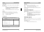
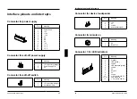
Parallel interface
1
13
25
14
The parallel interface supports three transfer modes: SPP, EPP and ECP. SPP
mode (standard parallel port) is the mode traditionally used to drive a printer. The
EPP (Enhanced Parallel Port) and ECP (Extended Capabilities Port) modes are
transfer modes that allow transfer rates of 2 and 2.4 Mbytes/s. These modes will
only work in connection with peripheral devices which specifically support them.
The new transfer modes are used among other things for connecting to SCSI or
IDE peripherals. The pinouts are different in all three modes.
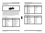
Pinout in SPP mode
Jack
Signal
name
Description
1
STROBE
Data message
2-9
Data Lines 0-7
Data lines 0-7
10
ACKNOWLEDGE
Data
acknowledgement
11
BUSY
Not ready to receive
12
PE
End of paper
13
SELECT
Device
selection
14
AUTO
Automatic new line
15
ERROR
Device
error
16
INIT
Reset/initialize
17
SELECT IN
Printer selection
18-25
GROUND
Ground
A26361-D858-Z120-6-7619
51
Interface pinouts and interrupts
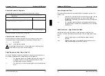
Pinout in EPP mode
Jack
Meaning
Signal
direction
1
Write
Output
2-9
Data Lines 0-7
Input/output
10
Intr
Input
11
Wait
Input
12
not
used
---
13
not
used
Input
14
DStrb
Output
15
not
used
---
16
not
used
---
17
AStrb
Output
18-25
Ground
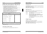
Pinout in ECP mode
Jack
Meaning
Signal
direction
1
HostClk
Output
2-9
Data Lines 0-7
Input/output
10
PeriphClk
Input
11
PeriphAck
Input
12
AckReverse
Input
13
Xflag
Input
14
HostAck
Output
15
PeriphRequest
Input
16
ReverseRequest
Output
17
ECP-Mode
Output
18-25
Ground
52
A26361-D858-Z120-6-7619

