NOTICE
Risk of cable damage due to mechanical loads
Cables that are exposed to mechanical loads, e.g. trailing chains or similar, must be suit-
ed for this purpose. Otherwise, damage may occur. SIEB & MEYERcables are not suit-
able for trailing chains!
→ The machine manufacturer must ensure that only cables are used that are suitable
for this purpose.
→ All cables used to connect the devices must be equipped with an appropriate strain
relief according to DIN EN 61800-5-1. This is particularly important, if no shield
connection clamps (SK 8-D, SK14-D Phoenix clamps) are used at the chassis
frame.
In general, the following principles apply for the cables (see also documentation “Unit
Assembly Complying EMC”)
▶
Motor and signal cables must not be wired in the same cable protection hose!
▶
Motor cables must have a wire-meshed shield. They must be wired separately from
signal cables.
▶
Signal lines must have a wire-meshed shield. Differential signals should only be
transmitted with twisted-pair lines. They must be wired separately from motor ca-
bles.
▶
The cable shields must be connected to the connector shell inside of the connec-
tors. In the switch cabinet they should be connected to a ground bus.
▶
Cable shields not ending in a connector inside of the switch cabinet such as motor
cables must be connected to the ground bus.
▶
Both ends of the shield of shielded cables must generally be connected to the shell.
The line cross-sections should be selected carefully so that the maximum admissible
current is not exceeded at the maximum ambient temperature (see technical data). DIN
EN 60204-1 defines the admissible values for the individual line cross-sections which
must absolutely be taken into account.
The current carrying capacity in connection with the line cross-section of copper con-
ductors isolated with PVC or cables according to DIN EN 60204-1 for different types of
wiring are indicated in the following table. All values are related to an ambient temper-
ature of +40 °C and an operating temperature at the conductor of 70 °C.
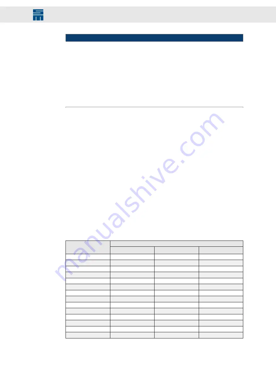
Admissible current I [A]
Conductor cross-
section A [mm²]
Wiring type B2
(1)
Wiring type C
(2)
Wiring type E
(3)
0.75
8.5
9.8
10.4
1.00
10.1
11.7
12.4
1.50
13.1
15.2
16.1
2.50
17.4
21
22
4
23
28
30
6
30
36
37
10
40
50
52
16
54
66
70
25
70
84
88
35
86
104
110
50
103
125
133
70
130
160
171
95
156
194
207
120
179
225
240
Tab. 12: Current carrying capacity according to DIN EN 60204-1
(1)
cable laying in installation tubes or closed installation channels on or under the wall surface or in chan-
nels for underfloor (multicore or sheathed cables)
(2)
direct cable laying on or under the wall/ceiling or in cable trays (multicore or sheathed cables)
61
Drive System SD4S - Hardware Description
Connectors


