Tools
Depending on the selected view, different tools are available to help you perform
configurations or customize the display.
The following are examples of some of the tools for customizing the display:
•
button: Change the device view. Device black: View from above, device blue:
View from below.
•
Button
or
: Switch off display of the full measuring line or display measur‐
ing line as dotted.
7.1.1
Parameter - network
The network area has input screens for configuring the Ethernet connection, the digital
inputs / digital outputs and the device.
For Ethernet configuration, note that the IP-Address / subnet-mask must correspond
with the address space of the subsequent application.
Table 9: IP-Address factory setting
Parameter
Value
IP-Address
192.168.0.1
Subnet mask
255.255.255.0
7.1.2
Parameter - filters
When selecting the filter, consider filter mutual interference,
7.2
Measurement data output
7.2.1
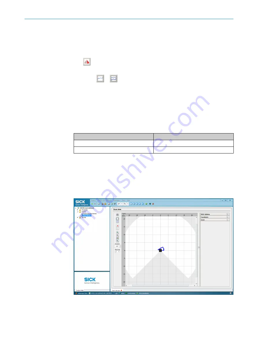
Monitor - scan view pro
Figure 20: Device window: Monitor - scan view pro
In the Pro scan display window, SOPAS displays the field contour (scan line) currently
seen by the device through ambient reflection in blue.
7
OPERATION
30
O P E R A T I N G I N S T R U C T I O N S | TiM4xx
8026151//2020-11-15 | SICK
Subject to change without notice


