SICK Safe Entry Exit Скачать руководство пользователя страница 44

12

Technical data

12.1

Data sheet

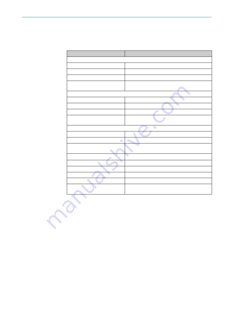
Table 15: Safe Entry Exit data sheet

Safe Entry Exit

For higher-level control with MTTFd value of at least 10 a

Performance level

PL d (ISO 13849-1)

Category

Category 3 (ISO 13849-1)

SIL claim limit

SILCL2 (EN 62061) 

PFHd (mean probability of one dan‐
gerous failure per hour)

2.15 × 10

–7

For higher-level control with performance level PL e

Performance level

PL e (ISO 13849-1)

Category

Category 3 (ISO 13849-1)

SIL claim limit

SILCL3 (EN 62061) 

PFHd (mean probability of one dan‐
gerous failure per hour)

4.53 × 10

–8

Safe Entry Exit manual muting function

Performance level

PL d (ISO 13849-1)

Category

Category 2 (ISO 13849-1)

PFHd (mean probability of one dan‐
gerous failure per hour)

5.34 × 10

–7

Supply voltage U

V

24 V DC (16.8 V DC ... 28.8 V DC) (SELV) 

1)

Ambient operating temperature

See operating instructions for the individual components

Storage temperature

See operating instructions for the individual components

Air humidity

See operating instructions for the individual components

Permissible operating height

See operating instructions for the individual components

Safe state

The safety-related semiconductor outputs are in the OFF
state.

1)

The external supply voltage must jumper a brief power failure of 20 ms as specified in IEC 60204-1. Suit‐
able power supply units are available as accessories from SICK.

12 

TECHNICAL DATA

44

O P E R A T I N G   I N S T R U C T I O N S | Safe Entry Exit

8021675/ZV26/2019-05-13 | SICK

Subject to change without notice

Содержание Safe Entry Exit

Страница 1: ...O P E R A T I N G I N S T R U C T I O N S Safe Entry Exit Safety System...

Страница 2: ...ble within the limits of the legal determination of Copyright Law Any modifica tion abridgment or translation of this document is prohibited without the express writ ten permission of SICK AG The trad...

Страница 3: ...ements for the electro sensitive protective device 13 3 5 Construction and function 14 3 6 Limits of the safety system 14 3 7 Functions 15 4 Project planning 16 4 1 Manufacturer of the machine 16 4 1...

Страница 4: ...tion 29 7 6 1 Configuration of Sequence monitoring 29 7 6 2 Configuration of Time monitoring 31 7 6 3 Configuration of PLC monitoring override 35 8 Commissioning 37 8 1 Safety 37 8 2 Thorough check 37...

Страница 5: ...Annex 48 15 1 Checklist for initial commissioning and commissioning 48 CONTENTS 8021675 ZV26 2019 05 13 SICK O P E R A T I N G I N S T R U C T I O N S Safe Entry Exit 5 Subject to change without noti...

Страница 6: ...information about the possible components of the Safe Entry Exit Table 1 Available documents Document type Title Part number Operating instructions Flexi Soft Modular Safety Controller Hardware 801299...

Страница 7: ...are organized by the life phases of the safety system project planning mounting electrical installation commissioning operation and main tenance 1 4 Symbols and document conventions The following symb...

Страница 8: ...instructions and mounting instructions of SICK components suitable for the safety system The Flexi Soft Designer configuration software Other configuration tools e g Excel tool Pre configured project...

Страница 9: ...r into the hazardous area The conveyor moves at a defined speed maximum of 4 different speeds during the transportation of the material The material is at least 500 mm long The length of the material...

Страница 10: ...trol and the Type 4 electro sensitive protective device is interrupted When the muting function is inactive the Type 4 electro sensitive protective device detects an object The voltage supply of the h...

Страница 11: ...re Flexi Soft safety controller main module Flexi Soft safety controller expansion module I O module 8 inputs 4 outputs Optional if the conveyor is going to switch between different speeds Flexi Soft...

Страница 12: ...tion of the pushbutton there must be a complete view of the hazardous area Activating the pushbutton must not initiate any movement of the machine The reset pushbutton must be designed in accordance w...

Страница 13: ...vel control and signal source must also correspond to PL e and have a MTTFd value of at least 100 a Measures must be taken with regard to the voltage supply for the higher level control so as to preve...

Страница 14: ...stop While the material is passing through the opening the safety controller continues to monitor the signals from the Type 4 electro sensitive protective device If the actual duration of the interrup...

Страница 15: ...necessary switches to the safe state see Muting function page 40 Time Extension Function After a correct initiation sequence of the muting function the maximum dura tion of the muting function can be...

Страница 16: ...has the following duties b Executing a risk assessment b Verifying and validating the safety functions b Integrating the individual components in accordance with the appropriate stan dards b Please n...

Страница 17: ...le The protective device is then not actuated during material trans port however people are still detected 4 4 Design This chapter contains information about implementing the design of the safety syst...

Страница 18: ...e risk assessment must determine to what degree people can misuse a process sig nal intended for transport goods in order to activate the muting function themselves by interrupting the Type 4 electro...

Страница 19: ...device If the risk assessment concludes that persons in front of the material definitely need more than 200 mm the distance can be adjusted accordingly 4 4 5 Calculating response times and stopping t...

Страница 20: ...Type 4 The electro sensitive protective device must conform to Type 4 and can be a safety light curtain for example Independent Control Sys tem The signals of the higher level control are part of the...

Страница 21: ...sessment Determination of the thorough checks must be documented in a traceable manner A thorough check must be carried out during commissioning and following modifi cations The regular thorough check...

Страница 22: ...nts 5 1 Mounting conditions for the electro sensitive protective device For mounting conditions see Type 4 electro sensitive protective device page 17 5 MOUNTING 22 O P E R A T I N G I N S T R U C T I...

Страница 23: ...nst overvoltage overcurrent etc according to the manufacturer s instructions for the individual components Mechanical fastening of the wiring of the pushbutton for the manual muting device e g with ca...

Страница 24: ...f timings need to be set for different con veyor speeds or different material sizes Table 6 Function of the connections Connection Function l1 S301 1 Timing 1 l2 S301 2 Timing 2 l3 S301 3 Timing 3 l4...

Страница 25: ...hese signals must be coded as 1 of n For more information see 1 of n timing sets page 43 Up to four timing sets can be configured and selected accordingly via signals The fol lowing table describes th...

Страница 26: ...is corresponds to the hardware configuration and logic of the project file with an activated Timing Set Selection function but it can be imported into any Flexi Soft CPU module firmware version 4 00 C...

Страница 27: ...rent timing sets can be selected sequentially using the Timing Set Selec tion function In the project file with a deactivated Timing Set Selection function Timing Set 1 is selected as standard Assumed...

Страница 28: ...n blocks with inputs and outputs Links connect these elements Links are represented as lines Every element contains blue anchor points which represent the inputs and outputs of the elements A link can...

Страница 29: ...ride All user defined function blocks in the safety related application software are locked and do not have to be configured Data relating to the speed of the conveyor and the size of the material bei...

Страница 30: ...iation is safety related If the risk assessment concludes that people in front of the material definitely need more than 200 mm of space the distance can be adjusted accordingly Termination network Fi...

Страница 31: ...sures that people located between or behind the material being transported will be detected The calculation of Tclearance and Ttermination is safety related 7 6 2 Configuration of Time monitoring Time...

Страница 32: ...for the following two networks the cycle time of this Clock generator function block is referred to as Tclock period We recommend setting the cycle time to around 100 ms Min time monitoring network F...

Страница 33: ...function block is reached with the pre set clock determines the minimum duration of the muting function The minimum duration of the muting function is calculated using the following formula The mater...

Страница 34: ...ed on the counting of peri ods in a defined clock with a defined overflow value The defined clock periods are set in the Time monitoring general network see Configura tion of Time monitoring page 31 T...

Страница 35: ...ulated minimum duration the safety sys tem goes into the error state 7 6 3 Configuration of PLC monitoring override Timing Set Selection Monitoring network Figure 9 Timing Set Selection Monitoring net...

Страница 36: ...l pathways when the function is used with 2 timing sets In this case the signals must be connected to the input with the same numbering pro ceeding in sequence All remaining inputs of the operating mo...

Страница 37: ...unting or the electrical connection After exceptional events such as after a manipulation has been detected after modification of the machine or after replacing components The thorough check ensures t...

Страница 38: ...NOTE Information is included in the operating instructions for the components 9 MAINTENANCE 38 O P E R A T I N G I N S T R U C T I O N S Safe Entry Exit 8021675 ZV26 2019 05 13 SICK Subject to change...

Страница 39: ...on delay timer Logic execution time 20 ms Activate the Logic execution time optimization option in Flexi Soft Designer Deactivate unnecessary functions e g Flexi Loop For more information see chapter...

Страница 40: ...ivate the muting function If the safety controller detects a deviation in sequence or timing the safe state is activated The only exception is if the protective field of the Type 4 electro sensitive p...

Страница 41: ...11 3 Time Extension Function Once the muting function is active after a correct initiation sequence the Time Exten sion TE signal can be used to extend the maximum duration of the muting function This...

Страница 42: ...material is interrupting the protective field of the Type 4 electro sensitive protective device This function can be activated exclusively by activating a spring back pushbutton Requirements for the...

Страница 43: ...ing function It allows the muting function to be set for different conveyor speeds and different material lengths This function is configured via timing sets that contain a value for every configured...

Страница 44: ...3849 1 PFHd mean probability of one dan gerous failure per hour 5 34 10 7 Supply voltage UV 24 V DC 16 8 V DC 28 8 V DC SELV 1 Ambient operating temperature See operating instructions for the individu...

Страница 45: ...Type 4 electro sensitive protective device used Table 17 Safe Entry Exit ordering data Type 4 electro sensitive protective device from SICK Product page deTec4 Prime www sick com deTec4_Prime deTec4...

Страница 46: ...lowing components are not included in the scope of delivery They must be selected as appropriate for the application and ordered separately Table 18 Safe Entry Exit ordering data Description Type code...

Страница 47: ...ety controller main module FX3 CPU000000 1043783 Flexi Soft safety controller expansion module I O module 8 inputs 4 outputs FX3 XTIO84002 1044125 Flexi Soft safety controller system plug FX3 MPL00000...

Страница 48: ...es No 1 4 Are functions of the Type 4 elec tro sensitive protective device that affect the direct correlation between the status of the protec tive field and the status of the output signal switching...

Страница 49: ...Result OK 1 After download or importing does the checksum of the Flexi Soft project match one of the check sums provided in Pre configured project files page 26 Yes No 2 1 If the Timing Set Selection...

Страница 50: ...the material Expected result safe state Yes No 5 3 If the Timing Set Selection func tion is used Are n times configured for Ttermina tion Yes No 6 Is the clock period of the upper clock generator func...

Страница 51: ...hat results in a time shorter than 10 min Yes No 9 2 If the Timing Set Selection func tion is used Are n counter function blocks in the Max time monitoring network configured for the maximum dura tion...

Страница 52: ...ico Phone 52 472 748 9451 E Mail mario garcia sick com Netherlands Phone 31 0 30 229 25 44 E Mail info sick nl New Zealand Phone 64 9 415 0459 0800 222 278 tollfree E Mail sales sick co nz Norway Phon...

Отзывы: