


WARNING
There is a risk of death or serious injury because the protective device cannot per‐
form the diagnostics function.
b
Always set a value greater than zero as the position ID because the position
0 mm is not permitted in this safety system for reasons relating to the diag‐
nostics.
•
If there are position ranges within the application that are not actually permitted,
these must also be defined.
The maximum possible measuring range of the respective sensor unit must be taken
into account too. Larger position values are not permitted.
Table 34: Maximum position range depending on sensor unit
OLM100 Hi, part number
1087575
OLM100 Hi, part number
1090629
Maximum position range
1,677 m
8,589 m
7.3.5
Assigning maximum speeds to the position ranges
1.
In the settings for the
Position Monitor
function block, move the mouse cursor to the
Speed-position-profile
button.
2.
Click on the
Speed-position-profile
button.
✓
The view opens. The
Speed-position-profile
window appears.
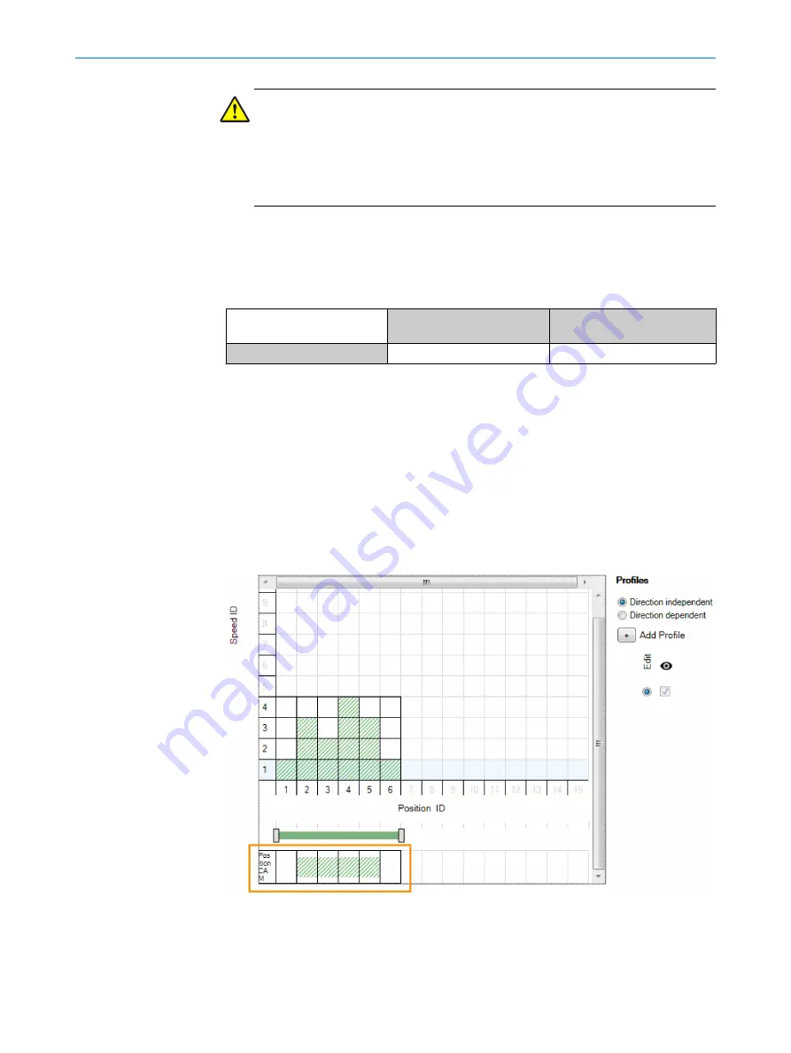
A maximum permitted speed (speed ID) can be set for each position range in order to
implement a safely limited speed (SLS) function. To do this, use the mouse to click on
the maximum permitted speed limit for each position range. Permissible speed ranges
below the speed limit are shown in green.
Example:
Figure 10: Profile settings for speed/position
In this example, the speed ID 1-4 speed limits are assigned to the position ID 1-6 posi‐
tion ranges.
CONFIGURATION
7
8020941/12O9/2019-08-05 | SICK
O P E R A T I N G I N S T R U C T I O N S | Safe Linear Positioning
41
Subject to change without notice


