background image

SYSTEM DESCRIPTION   


25 

8027513/V1-0/2022-03|SICK 

Subject to change without notice 

O P E R A T I N G   I N S T R U C T I O N S | MDA Vision 

3.10


Operating principle 


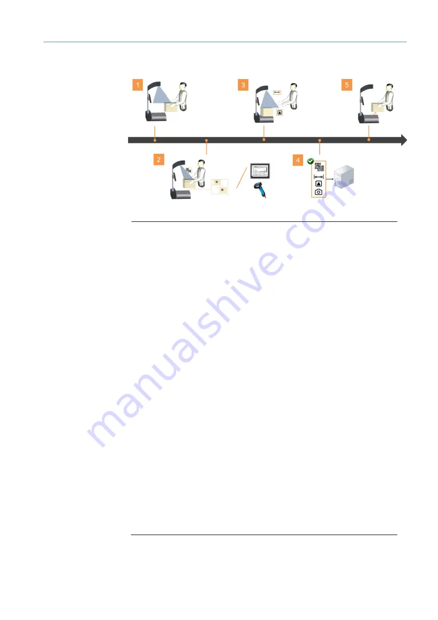
Fig. 19:  Operating principle  


Legend 

Starting measurement 


Bring the object into view of the 3D snapshot camera.  

The Lector6xx image-based code reader is activated. LED illumination and 
aiming laser are switched on. 

Automatic code reading 

MDA Vision is factory-supplied to decode a single code. The code can be of 
different types.  
If there are several codes on the object, they cannot be reliably detected.  

NOTE

 If special conditions or detection logics are required by the customer, 

contact SICK Service.  

Manual code reading 

Enter code on screen or record with mobile hand-held scanner if automatic 
code reading is unsuccessful. 

Measurement value determination 


Place the object on the scale after successful code reading. 


Release object.  

As soon as the object is free on the scale, weight and dimension values are 
determined and displayed. 


Data output and output of the camera images 

Immediate output of measurement and read data as well as camera 
images when a network connection is established. 
With the WLAN module available as an accessory, data can be output 
independently of the location.  

Completing measurement process 

Remove the object from the scale.  
All measured values are reset to zero. 


Содержание 8027513

Страница 1: ...OPERATING INSTRUCTION S Master Data Analyzer Vision ...

Страница 2: ...he associated rights are reserved by SICK AG Reproduction of this document or parts of this document is only permissible within the limits of the legal provisions of copyright law Any modification abridgment or translation of this document is prohibited without the express written permission of SICK AG The trademarks mentioned in this document are the property of their respective owners SICK All r...

Страница 3: ...tronic scale 18 3 5 Connection Box 19 3 6 Operating and reading unit 20 3 7 Optional components 21 3 7 1 IDM26x mobile hand held scanner 21 3 7 2 High resolution color camera 22 3 8 Accessories 23 3 8 1 WLAN module 23 3 9 Data output and output of the camera images 24 3 10 Operating principle 25 4 Transport setup and mounting 26 4 1 Transporting MDA Vision to the place of use 26 4 2 Unpacking MDA ...

Страница 4: ...tly 64 7 6 1 General notes 64 7 6 2 Notes on measuring non cubic objects 66 7 7 Error situations during measurement 68 7 7 1 No free measuring range after system start 68 7 7 2 No code reading 69 7 7 3 Object not placed in the reading field 70 7 7 4 Object too big too small 71 7 7 5 Custom Fields were not confirmed 72 7 7 6 No stable object weight 73 7 7 7 Scale is underloaded 74 7 8 Displaying la...

Страница 5: ...022 03 SICK Subject to change without notice O P ER A T I NG I NST R U C T I O N S MDA Vision 10 Notes and status messages 93 11 Technical data 94 11 1 Data sheet 94 11 2 Dimensional drawings 96 12 GEO codes 98 13 Disposal 100 ...

Страница 6: ...ation Unauthorized technical and other changes Use of unauthorized spare parts wear and tear of parts and accessories Unauthorized changes adjustments and or manipulations of software Failure to perform and document regular maintenance work The actual scope of delivery may differ from the features and illustrations shown here where special variants are involved or if optional extras have been orde...

Страница 7: ...K Lector65x Flex Focus QuickStart SICK Lector63x Flex C Mount QuickStart SICK IDM wired mobile hand held scanner QuickStart SICK BC shipping scale maintenance manual and certificate METTLER TOLEDO S16 Dual Flex operating instructions MOBOTIX SIM2000 2 P Sensor Integrated Machine operating instructions SICK MDA Vision QuickStart SICK Geo code table SICK Customer interface description SICK 1 6 Docum...

Страница 8: ...tem description in particular the safety notes as well as the repair and maintenance requirements The default state of the MDA Vision when shipped out of factory is set to decode a single code NOTE If multiple codes or special reading conditions are determined SICK Service should be scheduled to configure and commission the system 2 2 General safety notes Please read this document through carefull...

Страница 9: ... device does not pose a danger when viewed directly for up to 100 seconds It may pose a hazard to the eyes and skin in the event of incorrect use Never look directly into the laser beam Never point the laser beam at people s eyes During commissioning or maintenance work suitable eye protection must be worn Avoid laser beam reflectance caused by reflective surfaces in particular during mounting and...

Страница 10: ... Never enter the area under suspended loads Pay close attention when lifting loads Comply with lifting instructions to prevent injuries and accidents Use suitable undamaged lifting tools Wear personal protective equipment safety helmet safety shoes 2 5 Protective devices MDA Vision is built so that the system can be operated safely Protective devices reduce potential risks to the maximum possible ...

Страница 11: ...evented CAUTION Identifies a possibly hazardous situation which may lead to minor or moderate bodily injuries or material damage if not prevented NOTE Important information and useful notes 2 8 Warning symbols on the system components Warning labels must not be removed or covered up If labels are missing these must be affixed Damaged labels must be replaced Symbol Meaning Hazardous point warning H...

Страница 12: ...ent overview Fig 1 Component overview Legend 1 Base plate 2 Connection Box with system controller 3 Sensor head 4 Display for configuring the system and displaying the measurement results 5 Mobile hand held scanner for manual code reading optional 6 WLAN module for mobile use of the MDA Vision accessory 7 Rugged electronic scale for holding the measuring objects ...

Страница 13: ... 2 Sensor head components Legend 1 Visionary S 3D snapshot camera for determining dimensions and recording an image 1 megapixel 2 Lector65x or Lector63x image based code reader for code reading 3 Rugged color camera for high resolution images 6 megapixels of the measured object Prerequisite for cropping function Sensor head components ...

Страница 14: ...data at 30 frames per second fps The Visionary S 3D vision camera combines structured illumination with the proven technology of a color camera It delivers color depth images with more than 320 000 depth and color intensity values in just one shot The snapshot camera works similarly to a human pair of eyes Two cameras take two images of an object from two different positions and calculate the 3D d...

Страница 15: ...ra is evaluated The color information helps to detect the object in case of low contrast depth image information or background noise A 3D point cloud is generated based on the two pieces of image information This forms the basis for calculation of the dimension values The dimension results are transmitted to the system controller for further processing The Visionary S 3D camera records an image of...

Страница 16: ...nation ring for point shaped aiming laser Optical sensor with integrated LED illumination unit and dynamic focus control for code reading Allows the omnidirectional reading of bar codes on one side of an object even with varying object heights and code positions With the Lector65x an aiming laser creates a red cross in the field of view on the object and makes it easier to align the object for suc...

Страница 17: ...The code reading process starts as soon as the Visionary S detects a change in the field of view For the code decoding the reading field is lit up with a powerful LED illumination unit The code information on the photos is extracted and processed by the integrated decoding unit Transfer of the read code to the system controller for further processing Fig 11 Status indicators of the 6xx code reader...

Страница 18: ...weighing objects Weight determination after placing the object on base plate platter Transfer of the determine weight value to the system controller Display of the weight value together with the dimension values and the code in the measurement window of the MDA Vision display The separate scale display is installed in the base plate of the MDA Vision at the factory It makes it possible to set the ...

Страница 19: ...5 Electrical installation Contains the system controller the control unit of the MDA Vision The system controller coordinates the incoming and outgoing signals and processes the received measurement and read results Data output according to host telegram via Ethernet interface to the customer system If necessary separate output of camera images Visionary S high resolution camera LOSS OF THE RIGHT ...

Страница 20: ...egend 1 Status indicator 2 Displaying the measurement results 3 Visualization of the measurement process 4 Configuration area Touch sensitive screen Operating height is adjustable via the tube rod Used to input and output information Central visualization and operating unit of the MDA Vision It displays all measurement results and allows for convenient configuration of the system Features Function...

Страница 21: ...ll common stacked codes This connecting cable is used to both supply the mobile hand held scanner with voltage and transmit data Allows for manual code reading if the code cannot be read by the Lector6xx NOTE This can be the case if the code is too small Or with objects where the code is on the side of the object and it cannot be tilted by the operator for the measurement process either because it...

Страница 22: ...n color image of the object during the measurement process The photo is transmitted to the higher level customer system together with the measurement data as an alternative to the camera image from the Visionary S 3D snapshot camera The dynamic cropping function of the IP camera allows the camera images to be cropped for the object using the dimensioning data Focus on the measured object Helps red...

Страница 23: ...ousing The WLAN Ethernet Port Adapter has a circular polarized 5 dB directional antenna that also enables it to be used in surroundings with a high number of reflections from metals The WLAN Ethernet Port Adapter enables the Ethernet interface to be connected wirelessly to a WLAN access point This enables measurement results to be transmitted to the customer system when using the MDA Vision in a m...

Страница 24: ...le via FTP is possible The MDA Vision can be configured as a TCP client or as a TCP server 2 Output of the camera image with the measured object The color image from the Visionary S or optionally the high resolution image from the IP camera can be used The MDA Vision can be configured as an FTP client for the output of the camera image Output format and file names are preset by default see Custome...

Страница 25: ...l conditions or detection logics are required by the customer contact SICK Service Manual code reading Enter code on screen or record with mobile hand held scanner if automatic code reading is unsuccessful 3 Measurement value determination Place the object on the scale after successful code reading Release object As soon as the object is free on the scale weight and dimension values are determined...

Страница 26: ...to perform work assigned to them and to identify and avoid any potential dangers independently Electricians have the professional training skills experience and knowledge of the relevant standards and provisions needed to work on electrical systems and to detect and avoid any potential dangers independently 4 1 Transporting MDA Vision to the place of use MDA Vision is delivered in a sturdy box on ...

Страница 27: ...lifting equipment which is suitable for the weight and dimensions of the freight Never enter the area under suspended loads Pay close attention when lifting loads Comply with lifting instructions to prevent injuries and accidents Wear personal protective equipment safety helmet safety shoes Observe all local safety and work safety regulations 4 2 Unpacking MDA Vision MDA Vision is delivered partia...

Страница 28: ...CEE 7 VII 1x NEMA 1x C14 3 Sensor head with pre assembled sensors 4 Scale frame 5 Sheet metal cover 6 WLAN module accessory 7 Mobile hand held scanner optional 8 Bag with screws and small parts Remove the components and accessories from the packaging and assemble them as described below Screws for mounting the sensor head see section 4 3 3 Mounting and connecting sensor head Key for the PortLock s...

Страница 29: ...ring assembly work The device tipping over can lead to the severe crushing or even loss of limbs There is also the risk of inflicting damage to the device Place the base plate on a stable and non tilting table Secure the table to prevent rolling away DANGER DANGER OF CRUSHING WHEN SETTING DOWN THE BASE PLATE The adjustable feet are designed so that the safety distance between the bottom of the dev...

Страница 30: ... base plate where it is then connected and assembled Fig 24 Base plate pre assembly factory Legend 1 Positioning area 2 Scale display 3 Connecting cables The scale display is pre assembled in the base plate Three cables for connecting the electronic scale are led out of the base plate at the factory Place the scale frame on the base plate Fig 25 Placing scale frame on base plate Pre assembly facto...

Страница 31: ...late to allow access to the connection unit To do this grasp the scale frame at the front with both hands and tilt it upwards like a lid Fig 26 Tilting the scale frame to connect the cables Hold the upright scale with one hand in the tilted position Connect the cables to the connection unit as follows Fig 27 Connecting the cables to the connection unit of the scale Legend 1 Connection of scale dis...

Страница 32: ...evice NOTE The scale is equipped with a leveling bubble If the bubble is inside the circle Fig 29 left the scale is levelled otherwise if the bubble is not completely inside the circle Fig 30 right then continue maneuvering the feet until desired outcome is achieved Fig 31 Display of the leveling bubble Adjust the feet so that the scale is stable and does not wobble After leveling tighten hexagon ...

Страница 33: ... LOADS The sensor head weighs up to 9 kg depending on the number of sensor components installed at the factory There is a risk of injury from suspended loads and damage to the sensor components during mounting Perform mounting with 2 persons Lift the sensor head in line with ergonomic principles Wear safety shoes in addition to personal protective equipment Fig 33 Support tubes pre assembly at the...

Страница 34: ...ead into the recess of the mounting plate of the support tube using the suspension screw The sensor head is then in the correct mounting position and is secured against tipping out Fig 34 Hooking sensor head into mounting plate Remove the two M6 screws from the bag and use them to screw the sensor head to the mounting plate Hand tighten the suspension screw and the fixing screws Fig 35 Screwing do...

Страница 35: ...nary S 3D snapshot camera 2 Connection area of Lector6xx 3 Connection area of color camera Guide the connecting cables into the terminal compartment of the sensor head NOTE The cables are already connected to the controller Connect cables to the sensor components Fig 37 Connection of 3D snapshot camera Connection Function 1 Ethernet 2 Voltage supply Connecting sensor components Connection of 3D sn...

Страница 36: ...ector connection Connection Function 1 Voltage supply 2 Ethernet Remove the blue locking cap on the back of the camera by turning it clockwise Insert the mini USB male connector into the female connector on the back of the camera Screw the blue locking cap back on Fig 39 Color camera connection Connection of Lector65x Color camera connection optional ...

Страница 37: ...see section 5 4 Connecting mobile hand held scanner optional 4 3 5 Mounting the WLAN module accessories Fig 41 Mounting the WLAN module accessory The WLAN module available as an accessory is attached directly to the housing of the MDA Vision The housing wall has two drill holes with the required spacing on the Connection Box to accommodate the WLAN module Two fixing screws are included with delive...

Страница 38: ...xperience and knowledge of the relevant standards and provisions needed to work on electrical systems and to detect and avoid any potential dangers independently DANGER HAZARDOUS ELECTRICAL VOLTAGE The system is supplied with mains voltage via an external power supply unit Risk of electrical shock Contact will result in death burns or shock Electrical work may only be performed on the system by qu...

Страница 39: ...LAN module available as an accessory 4 Service Ethernet port for connecting a service computer 5 Data Ethernet port for connecting the MDA Vision to the customer system 6 Power 24 V Connection of the MDA Vision to the local voltage supply via the supplied power supply unit Fig 43 Port lock with key The service port is mechanically locked with a port lock upon delivery for cyber security reasons Th...

Страница 40: ...s are included in the scope of delivery The MDA Vision is connected to the local voltage supply The connection is made via the industrial power supply unit included in the scope of delivery All components of the MDA Vision are supplied with voltage via the power supply unit Fig 45 Establishing connection to the voltage supply Connect the OUTPUT cable to the power supply unit and plug it into the P...

Страница 41: ...Data connection socket NOTE The Ethernet cable is not included in the scope of delivery Lead the cable to a free Ethernet female connector of the target network Establish Ethernet connection with the target network 5 4 Connecting mobile hand held scanner optional Fig 47 Connecting mobile hand held scanner optional Plug the plug connector of the cable coming out of the mobile hand held scanner into...

Страница 42: ...e supply voltage of the MDA Vision to power the WLAN adapter 2 Connection to the data interface Screw the supply voltage connecting cable of the WLAN module onto the Power male connector Connect the other end of the cable to the Aux 24V connection on the MDA Vision Screw the Ethernet cable on the WLAN module onto the LAN male connector Plug the other end of the cable on the MDA Vision into the Dat...

Страница 43: ...tems and to detect and avoid any potential dangers independently 6 1 Switching on MDA Vision All components of the MDA Vision are started together Make sure that there is no object on the scale Switch on MDA Vision All system components of the MDA Vision are booted up and checked for operational readiness in a self test The start up process takes about 30 seconds without separate camera During the...

Страница 44: ...1 Basic system settings Basic system settings are made on the Time Units page Enter the current date and time On this basis all measurement and read data determined by the MDA Vision are then provided with a time stamp Select units of measurement for the dimension and weight values The units of measurement defined here for dimensioning and weight determination apply and are reflected in the measur...

Страница 45: ...m the address range of the customer network and define subnet Activate the Use DHCP option if the IP address of the MDA Vision is to be obtained automatically via a DHCP server The obtained IP address is displayed in the IP Address field NOTE The input fields for the IP address are grayed out and blocked for input If necessary add the IP address of the gateway if a connection is to be established ...

Страница 46: ...dapted to the specific situation on site Click on Start calibration The current height reference of the Visionary S 3D camera is determined Before starting the calibration a note appears stating that the calibration requires a free measuring range Clear the scale if not already done and move your hands out of the field of view of the 3D camera Calibration starts automatically after 5 s Calibration...

Страница 47: ...image based code reader is already set at the factory The color camera is also already set up at the factory Confirm successful calibration of the 3D camera with OK Click on Calibrate scale The window for calibrating the scale is displayed Click on Start Scale calibration You will receive appropriate instructions for entering the GEO code in the Mettler Toledo scale display found inside the scale ...

Страница 48: ...location of the scale Press the or arrow keys to scroll through the code numbers The numbers repeat themselves The appendix contains a list of all regions and the corresponding GEO codes see section 12 GEO codes Press ENTER pushbutton to accept the selection The scale is restarted and displays 0 00 After input immediately replace the sheet metal cover so that the correct zero weight can be determi...

Страница 49: ... Code recoding can only be performed with a connected mobile hand held scanner In the Active Decoders area select all code types that are to be decoded in principle NOTE Specifying multiple active decoders slows down the reading process since the corresponding codes must be searched for in the image If a mobile hand held scanner is connected a configuration code 2D is displayed on the right side R...

Страница 50: ...P client Server IP to connect IP address of the client to which the MDA Vision must connect Server port Port through which the MDA Vision communicates with the client The MDA Vision can alternatively be configured as an FTP client The file name and the file extension are fixed see the Customer Interface Description supplement NOTE Either TCP IP OR FTP data transmission is possible Both transmissio...

Страница 51: ...ld provide the camera images As a rule this is the Visionary S 3D camera Activate Image Cropping if the camera image is to be cropped to the image section with the measured object NOTE This is only possible if the entry IP Cam was selected in the Source field Configure MDA Vision for image output as FTP client for settings see section 6 2 5 Configuration of the data output Depending on the applica...

Страница 52: ...2022 03 SICK O P ER A T I NG I NST R U C T I O N S MDA Vision Subject to change without notice 6 2 7 Completing initial commissioning Click Finish The installation wizard is closed automatically and the measurement window is displayed ...

Страница 53: ...user interface Legend 1 Menu bar 2 Navigation bar 3 Image area 4 Result line 5 Status bar The menu bar contains the following icons Allows switching to the configuration area Switches back to the measurement window Displays the currently selected working range Displays the current user level Allows changing of the user level The navigation bar allows you to switch between the individual working ra...

Страница 54: ...ic scale to be manually set to zero weight value The status bar contains information on the system status current measurement status and connection status The display is made of colored symbols as well as a short description A blue symbol with the Ready for next measurement indicates readiness for operation The first measurement can be started An existing connection to the customer system is visua...

Страница 55: ... measurement Bring the object into view of the 3D snapshot camera NOTE Only position one object at a time Fig 50 Positioning and measuring object As soon as the Visionary S registers a change in the field of view the image based code reader is activated LED illumination and aiming laser are switched on The measuring object becomes visible in the two windows Display ...

Страница 56: ... right image continues to display the current measurement situation The red coloring of the object and hand visualizes that the prerequisites for weight and dimension determination have not yet been met Successful code reading is visualized as follows The left image display with the codes is outlined in The read code is also outlined in in the camera image The read code information is displayed ab...

Страница 57: ... on the scale weight and dimension values are determined and displayed A successful determination of weight and measurement is visualized as follows The measuring station display is outlined in green after the measured value has been successfully determined The measured object is displayed in green Everything that is not assigned to the measuring object is colored red in the measuring station disp...

Страница 58: ...ng the object from the scale All measured values are reset to zero The left image display is empty The measuring station display provides an up to date live image The Ready for next measurement note appears in the status bar Start the new measurement process To do this place the object in the viewing range of the Visionary S see section 7 2 1 Starting measurement Display Starting next measurement ...

Страница 59: ...the hand held device requires that it has been connected and configured see section 6 2 4 Code reading configuration Place the object on the scale Remove the mobile hand held scanner from the bracket Press the trigger on the scanner handle to activate the scanner light source Fig 54 Scanning code with mobile hand held scanner Aim the laser beam at the code A beep indicates that the code has been r...

Страница 60: ... range of the Lector If there is no successful code reading in the set time the pop up window opens Type the code manually into the field using the keyboard that appears Confirm with SUBMIT The pop up window will close The manually entered code is shown without the camera image in the left image window NOTE As an alternative to manual code entry in the pop up window the connected mobile hand held ...

Страница 61: ...I NST R U C T I O N S MDA Vision Skip the entry of a code with SKIP e g if no code is available and it is to be added later in the customer system and assigned to the data record The pop up window will close No bar code is shown Weight and dimension values are determined Skipping code entry ...

Страница 62: ...c data is transmitted to the customer system together with the object master data after the measurement If additional fields have been configured the change to the Custom Fields tab takes place immediately after the measurement value determination has been completed The defined additional fields are either empty or they contain the entries made before the last measurement For configuration of the ...

Страница 63: ... are required It is mandatory to make an entry here Confirm input with Confirm NOTE The button is not active until all mandatory fields have been filled in The switch back to the Live View takes place The measurement results are automatically transmitted to the customer system together with the additional information in a data record Remove object from scale Start new measurement Process Next step...

Страница 64: ...Center placement of the object Avoid interruptions e g by hand during the measurement process in order not to falsify the measurement results Fig 56 No interruptions during the measurement process Ensure a clearance of at least 200 mm on both sides of the scale Do not place any objects there to avoid influencing the measurement Fig 57 Clearance on both sides of the scale General rule Center placem...

Страница 65: ... R U C T I O N S MDA Vision Avoid direct sunlight on the scale so as not to influence the measurement results Fig 58 Avoid direct sunlight Uniform ambient light is required for good image color quality Fig 59 Uniform ambient light for good color quality Avoid direct sunlight Uniform ambient light ...

Страница 66: ...t valid in these cases NOTE The illustrations below show an object in two dimensions in the front view This applies equally in three dimensional space When measuring non cubic objects make sure that the object is not shadowed and has all sides visible to the camera NOTE Edges that cannot be seen by the 3D Visionary S due to shading are not considered in the contour detection and are not included i...

Страница 67: ...rate separation of object and background Fig 62 Non angular transitions to the footprint If parts of non cubic objects are lower than the allowed minimum object height these parts are not considered in the dimensional measurement The measured object in this case is smaller than the real object Fig 63 Object parts lower than object minimum height Non angular transitions to the footprint Object part...

Страница 68: ... up with an object on the scale A weight value is displayed after start up The Please free measurement area at startup appears in the status bar The scale surface must be free when the MDA Vision is started up as this is the reference for height determination Remove the object from the scale The Ready for next measurement note appears in the status bar The MDA Vision is now ready for operation Err...

Страница 69: ...e code is too small This can happen especially with flat and small objects Remove the object from the scale again This starts a new measurement process Hold the object in the reading field at a small distance from the Lector The red laser dots or the red laser cross visible on the object make it easier to align the object for successful code reading As soon as the code could be read it is displaye...

Страница 70: ...the measuring field The Place object centered on scale for measurement appears in the status bar Parts of the object are not in the field of view of the Visionary S 3D camera Dimensional values cannot be determined Move object on the scale so that all object areas are in the Visionary S field of view As soon as the identified object has been correctly placed on the scale weight and dimension value...

Страница 71: ...ge appears in the status line each with a note indicating which dimension does not correspond to the permissible dimensions In the figure above the object width is smaller than the minimum width allowed One or more object dimensions exceed or fall short of the permissible dimensions The object is too large or too small Only measure objects whose dimensions correspond to the technical data Error de...

Страница 72: ...layed However in the status bar the Commit custom fields appears The measurement requires the input of additional information This was entered in the Custom fields tab but not confirmed Switch to the Custom fields tab Tap the Confirm button The program automatically switches to the Live view tab In the status bar the Measurement successful note appears Error description Fault cause Solution ...

Страница 73: ...in 5 seconds Vibration in the working environment Draft in the immediate vicinity Remove the object from the scale This initiates a new measurement process Place the object in the center of the scale Once the code is read weight and dimension values are determined NOTE If a weight value still cannot be determined make sure that the MDA Vision is set up in a stable and vibration free manner and tha...

Страница 74: ...ro However the weight value is displayed with the addition underload in red font The electronic scale shows underload This may occur if very light objects were measured and the scale cannot be reset to zero after the measurement process In the measurement window tap the Zero button The weight value of the scale is set to zero The display of the zero value appears in blue letters Error description ...

Страница 75: ...associated camera image at any time Click on the Logs tab in the navigation bar of the measurement window The measurement results are listed line by line Each message has a unique ID and a time stamp Select the measurement in the list and tap the Show selected object button The camera image of the measurement is displayed with the determined code s Close the image window with OK Measurement result...

Страница 76: ...omer specific input fields A detailed analysis of the stored camera images of a measurement Tap the person icon in the title bar of the window Select user level and enter password using the keyboard that appears User Password Service Service level Confirm input with login The measurement window is displayed in configuration mode The selected user level is displayed to the right of the person icon ...

Страница 77: ...d in the configuration area Tap the content icon in the menu bar The content tree of the configuration area is opened The measurement window is shifted to the right In the content tree tap CONFIGURATION The measurement window is hidden The settings are grouped thematically in individual tabs The tabs correspond to the respective pages in the installation wizard Tap the content icon again The conte...

Страница 78: ...on wizard see section 6 2 1 Basic system settings Field Explanation Calibrate device Enables calibration of the Visionary 3D camera see section 8 3 Performing post calibration Tare option Displays the Tare button in the measurement window for taring the scale 8 2 2 Network settings The fields in the Network tab correspond to the fields on the page of the same name in the installation wizard see se...

Страница 79: ...ration Field Explanation Enable Activates the display of the pop up window after a defined timeout for manual entry of the code see section 7 4 Enter code manually or skip code reading Popup time Defines the amount of time to wait until the pop up window is displayed after code reading has not taken place 8 2 4 Configuration of the data output The fields in the Output Data tab correspond to the fi...

Страница 80: ...ields to add customer specific information to the master data A distinction is made between text fields numeric fields and selection lists Up to six additional fields can be activated and configured The additional fields are automatically displayed after a successful measurement if they are activated If no additional field has been activated the Custom Fields tab will not be displayed The detected...

Страница 81: ... fields and numeric fields do not require any additional information List boxes must be configured in a separate step Mandatory Specifies whether the field is a mandatory field that requires mandatory input Reset after scan Defines whether the additional field should be preset with the input of the last measurement Selection lists give users a list with fixed entries from which they can select an ...

Страница 82: ...a the pencil icon Tap the X in the list entry field The entry is removed from the list Delete All removes all entries from the list 8 2 7 Select language Show content tree of the configuration area via the menu bar In the content tree tap LANGUAGE Select user language Tap the Home icon in the menu bar The measurement window is displayed The content tree of the configuration area is automatically h...

Страница 83: ...a different measuring location recalibrating the Visionary S 3D camera is recommended Show content tree of the configuration area via the menu bar In the System tab tap Calibrate device A note appears stating that the calibration requires a free measuring range Remove the object from the scale if you have not already done so and move your hands out of the 3D camera s field of view Calibration star...

Страница 84: ...ATION 84 8027513 V1 0 2022 03 SICK O P ER A T I NG I NST R U C T I O N S MDA Vision Subject to change without notice A message window informs about the successful completion of the calibration Click OK to confirm ...

Страница 85: ...otential dangers independently Device Maintenance task Interval Type Visionary S Clean the front screen 1x month Trained personnel Lector6xx Clean the front screen 1x month Trained personnel Color camera Clean the front screen 1x month Trained personnel Scale Visual monitoring for contamination Daily Trained personnel General information Visual monitoring for contamination Daily Trained personnel ...

Страница 86: ...on must be worn Avoid laser beam reflectance caused by reflective surfaces In particular during mounting and alignment work Do not open the housing Current national regulations regarding laser protection must be observed WARNING DANGEROUS LED RADIATION The Lector 6xx image based code reader operates with RG1 risk group LEDs Visible radiation 400 nm to 780 nm The LEDs may pose a danger to the eyes ...

Страница 87: ... wipe the front screen with a clean damp lint free cloth Use a mild anti static lens cleaning fluid if necessary CAUTION REDUCED READING PERFORMANCE DUE TO SCRATCHES OR STREAKS ON THE OPTICAL BOUNDARY SURFACE The optical output is weakened by scratches and streaks on the optical boundary surface Do not use aggressive cleaning agents Do not use abrasive cleaning agents Avoid any movements that coul...

Страница 88: ...ust be worn Avoid laser beam reflectance caused by reflective surfaces In particular during mounting and alignment work Do not open the housing Current national regulations regarding laser protection must be observed WARNING DANGEROUS LED RADIATION The Lector 6xx image based code reader operates with RG1 risk group LEDs Visible radiation 400 nm to 780 nm The LEDs may pose a danger to the eyes in t...

Страница 89: ...ing plate 2 Terminal blocks 3 Clamping screws Switch off the device using the main switch of the MDA Vision Unscrew all connecting cables from the defective device Unscrew and remove the clamping screws on both sides Fig 66 Loosening and removing clamping screws Tilt the camera away from the front Slide the camera upward and unhook it from the clamping blocks Fig 67 Unhooking the camera from the c...

Страница 90: ...g the main switch of the MDA Vision Unscrew all connecting cables from the defective device Loosen and remove the four fixing screws on the mounting plate NOTE When loosening the last screw press the Lector against the mounting plate with one hand to fix the device Remove the defective Lector from the bracket The mounting plate remains mounted on the frame of the sensor box Fig 69 Removing the mem...

Страница 91: ... see section 4 3 3 Mounting and connecting sensor head 9 3 3 Replacing color camera Fig 70 Replacing color camera Legend 1 Cable fuse 2 Mounting plate 3 Camera lens Switch off the device using the main switch of the MDA Vision Unscrew the connecting cable from the defective device Screw on the counter nut NOTE Hold the camera with the other hand Pull the camera forward out of the mounting plate Pl...

Страница 92: ...ce 9 4 Cleaning the Connection Box Fig 71 Cleaning the Connection Box Remove the plate from the scale The air grille of the Connection Box is now accessible Clean the air grille with a brush Vacuum coarser contaminants with an industrial vacuum cleaner WARNING RISK OF DAMAGE TO ELECTRONIC DEVICES Never use compressed air for cleaning ...

Страница 93: ...ming laser An object was brought into the field of view of the sensors But the Lector could not read a bar code See section 7 7 2 No code reading Please free measurement area at start up The system was started up with an object on the scale See section 7 7 1 No free measuring range after system start Object too big DIMENSIONS One or more object dimensions exceed the allowed dimensions See section ...

Страница 94: ...ption available 100 g 60 kg Non LFT resolution d 5 g 0 15 kg 10 g 15 30 kg 20 g 30 60 kg LFT resolution e 20 g 100 g 60 kg up to 2 g optional reduced throughput Maximum latency time for data output max 1 500 ms for output of all master data dimensions weight code image for standard configuration Lector654 single code etc after code was read no intrusion detected and stable weight available Output ...

Страница 95: ...non transparent Object consistency Dimensionally stable and detectable all sides must be visible No touching by operator during measurement Surrounding conditions Best measurement results are achievable if object is placed in the center of the scale Avoid direct sunlight on scale to improve results Ensure a free space of min 200 mm on both sides of the scale no objects placed to avoid influences o...

Страница 96: ... 03 SICK O P ER A T I NG I NST R U C T I O N S MDA Vision Subject to change without notice 11 2 Dimensional drawings Fig 72 Dimensional drawing of MDA Vision front view Fig 73 Dimensional drawing of MDA Vision side view Front view Side view ...

Страница 97: ...TECHNICAL DATA 11 97 8027513 V1 0 2022 03 SICK Subject to change without notice O P ER A T I NG I NST R U C T I O N S MDA Vision Fig 74 Dimensional drawing of MDA Vision top view Top view ...

Страница 98: ...1 1 12 44 15 6 6 6 5 5 4 4 3 3 2 2 1 15 6 17 0 7 6 6 5 5 4 4 3 3 2 2 17 10 19 2 7 7 6 6 5 5 4 4 3 3 2 19 2 20 45 8 7 7 6 6 5 5 4 4 3 3 20 45 22 22 8 8 7 7 6 6 5 5 4 4 3 22 22 23 54 9 8 8 7 7 6 6 5 5 4 4 23 54 25 21 9 9 8 8 7 7 6 6 5 5 4 25 21 26 45 10 9 9 8 8 7 7 6 6 5 5 26 45 28 6 10 10 9 9 8 8 7 7 6 6 5 28 6 29 25 11 10 10 9 9 8 8 7 7 6 6 29 25 30 41 11 11 10 10 9 9 8 8 7 7 6 30 41 31 56 12 11 1...

Страница 99: ... 13 52 22 21 20 20 19 19 18 18 17 17 16 16 52 22 53 31 21 21 20 20 19 19 18 18 17 17 16 53 31 54 41 22 21 21 20 20 19 19 18 18 17 17 54 41 55 52 22 22 21 21 20 20 19 19 18 18 17 55 52 57 4 23 22 22 21 21 20 20 19 19 18 18 57 4 58 17 23 23 22 22 21 21 20 20 19 l9 18 58 17 59 32 24 23 23 22 2 2 21 21 20 20 19 19 59 32 60 49 24 24 23 23 22 22 21 21 20 20 19 60 49 62 9 25 24 24 23 23 22 22 21 21 20 20...

Страница 100: ...nce with international directives and regulations batteries accumulators and electrical or electronic devices must not be disposed of with household waste The owner is obligated to dispose of the devices at the end of their service life via the appropriate public disposal points This icon on the product packaging or in this document indicates that a product is covered by these provisions The follo...

Страница 101: ...port sick jp Malaysia Phone 603 8080 7425 E Mail enquiry my sick com Mexico Phone 52 472 748 9451 E Mail mario garcia sick com Netherlands Phone 31 0 30 229 25 44 E Mail info sick nl New Zealand Phone 64 9 415 0459 0800 222 278 tollfree E Mail sales sick co nz Norway Phone 47 67 81 50 00 E Mail sick sick no Poland Phone 48 22 539 41 00 E Mail info sick pl Romania Phone 40 356 17 11 20 E Mail offic...

Отзывы: