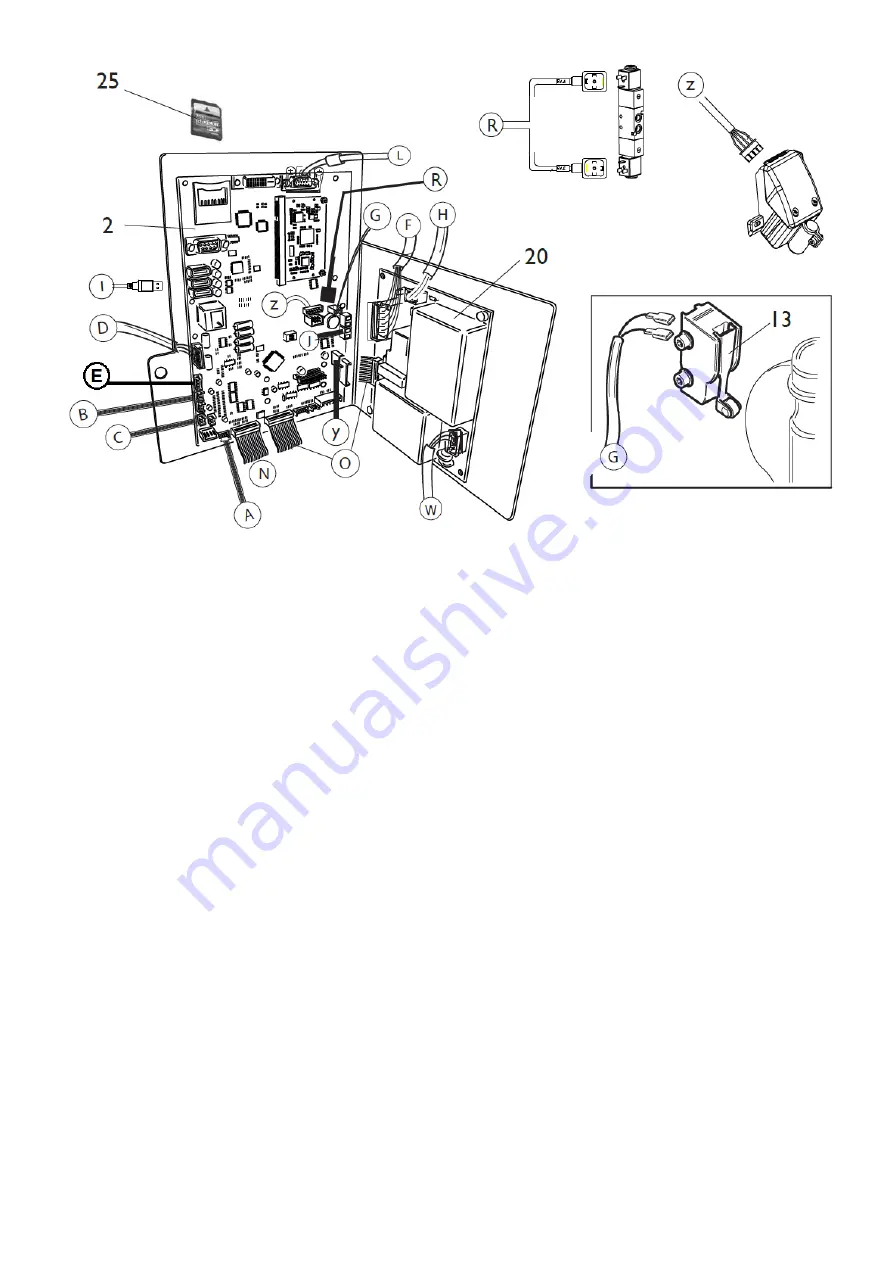
fig. 3
5.1 PEAL 32F power board
This power board enables the wheel balancer to be powered with single phase AC mains power with a voltage of 100 - 240 Volts +/- 10% (20
fig.3).
The following LEDs must illuminate after power-on:
- LED LD1 (green) must be lit (indicates that board is receiving 5VDC power),
- LED LD20 (green) must be lit (indicates that Sonar sensor is receiving 24VDC power),
if these LEDs are not lit, check that the board is receiving power correctly.
The following red LEDS light up in sequence when a spin is performed:
• LD2 indicates the power supply to the spin motor (115/230VAC);
• LD3 indicates the end of spin braking with inversion of current mode;
• LD4 FR_ST indicates clamping braking or braking in a centred position if the RPA programme is enabled.
5.2 “MBUGRF” CPU board
- LD1 = green +5V board power supply presence LED
- LDG35 = Graphic module output green +3.3V power supply presence LED (if off, problem with graphic module)
the other LEDs must always be off (currently not managed)
If the LED is off, check the following in the order given:
- that the PEAL32F board is functioning correctly;
- that the power cable from the PEAL32F board (O, Fig.3) is connected correctly.
- replace the power cable (O, Fig.3);
- replace the MBUGRF board (2, Fig.3);.
TEST POINTS ON BOARD
U10 +5V =
+4.75V to +5.25V
NOTE
The SD board on the MBUGRF (25, Fig. 3) must be configured as shown in figure 4 (NO LOCK).
Otherwise, the machine will NOT acquire any changes/settings.
Содержание S 64E
Страница 43: ...Fig 20 fig 21...
Страница 45: ......
Страница 46: ...SECOND VERSION OF PNEUMATIC SYSTEM from April 2016...
Страница 47: ...THIRD VERSION OF PNEUMATIC SYSTEM from March 2017...
Страница 48: ...FOURTH VERSION OF PNEUMATIC SYSTEM...
Страница 50: ...PEAL 32F...
Страница 51: ......
Страница 52: ...MBUGRF 2 LIGHT...
Страница 53: ......
Страница 54: ...COMIM Cod 4 119446B_EN 05 2018...


