background image

ESPANOL • Manual de instrucciones

97

S 42

autocentrante en sentido horario. 

El sentido de rotación antihorario sirve solamente para rectificar eventuales errores del operario.

RUEDAS ESPECIALES

El S 42 equipado con accesorios específicos, disponibles bajo pedido, está en condiciones de operar en ruedas especiales: PAX SYSTEM 

(con PT+KPX), SR Support Ring (con PT+KSR), Run Flat, rebajadas y UHP (con PT). Los procedimientos para operar correctamente en 

dichas ruedas son ilustrados en el manual de instrucciones que acompaña al accesorio específico.

10.5 TALONADO Y INFLADO


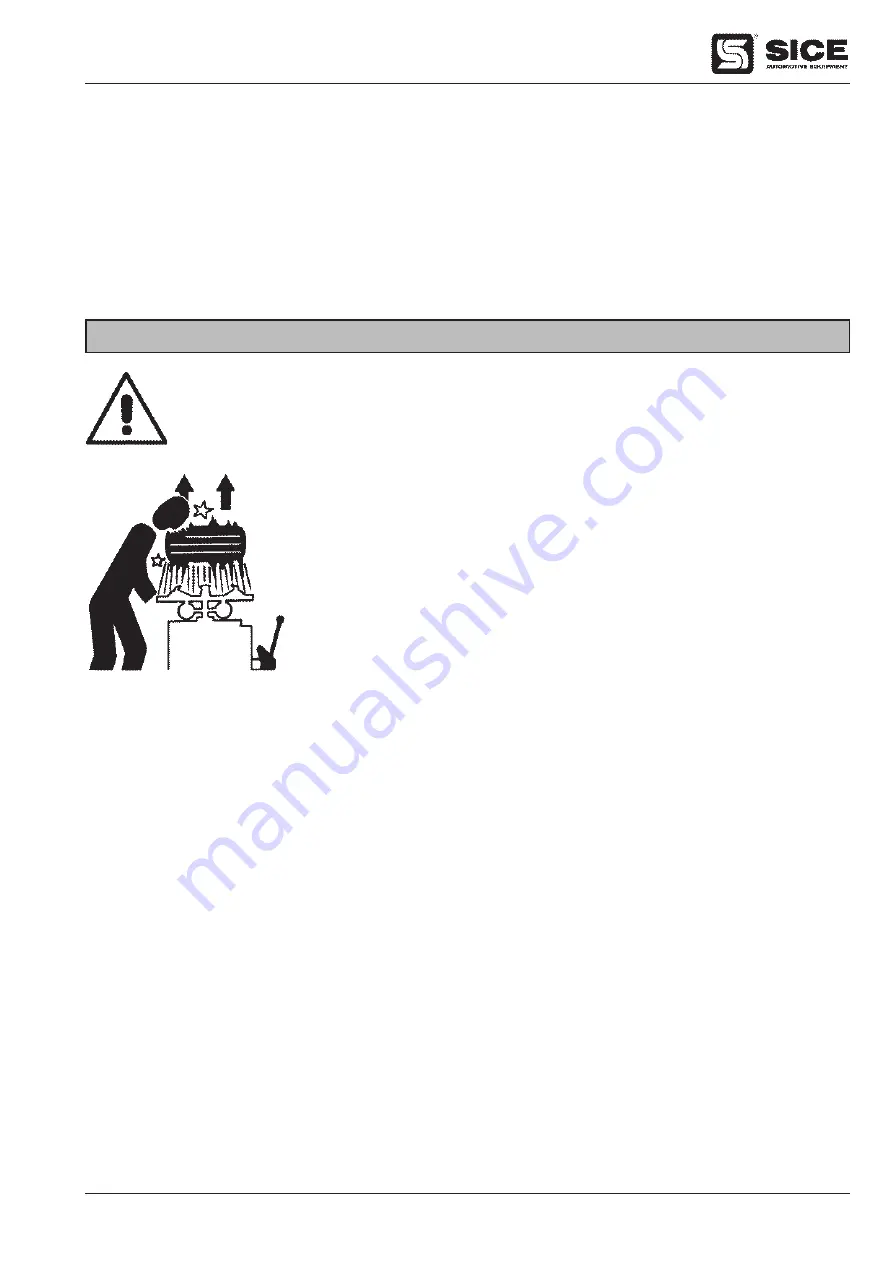
PELIGRO !!


El inflado de los neumáticos es peligroso! 


Seguir escrupulosamente las advertencias e instrucciones 

  ATENCION !


La rotura de una llanta o de un neumático bajo presión puede provocar una explosión que  


proyecta la rueda lateralmente o hacia arriba con tal fuerza que puede causar daños, serias


lesiones o incluso la muerte !. 


             No obstante esta desmontadora está dotada de un limitador de presión tarado a 3,5 Bar 


(50 PSI), esto no es un dispositivo de seguridad y no asegura eliminar riesgos y daños de una   


eventual explosión.

UNA RUEDA PUEDE EXPLOTAR CUANDO:

1) El diámetro de la llanta no es exactamente igual al diámetro del neumático.

2) La llanta o el neumático son defectuosos.

3) Durante el talonado se supera la presión máxima recomendada.

4) El neumático es inflado superando la presión máxima indicada por el fabricante.

5) El operario no guarda las oportunas normas de seguridad.

ATENCION: Las operaciones descritas en este párrafo se refieren a una máquina dotada de pistola de inflado.

Operar de la siguiente forma:

1)

 Desmontar el tapón y el interior de la válvula.

2)

 Introducir en la válvula la uñeta de inflado verificando que se enganche correctamente.

3)

 Verificar de nuevo la exacta correspondencia de los diámetros de llanta y neumático.

4) 

Verificar que la llanta y el neumático estén perfectamente lubricados, eventualmente volver a lubricar.

5)

 Talonar introduciendo aire a breves impulsos verificando continuamente, en intervalos, la presión en el manómetro de la pistola de inflado, 

hasta que los talones no estén alojados en los correspondientes alojamientos. Se debe poner particular atención y cuidado en el talonado de 
cubiertas sobre llantas dotadas de borde antidestalonantes (HUMP, DoBLE HUMP, etc.).

6) 

Proseguir, siempre introduciendo aire a breves golpes y siempre verificando en los intervalos la presión, hasta conseguir la presión de-

seada.

Содержание S 42

Страница 1: ...TOMATIC TYRE CHANGER DEMONTE PNEUS AUTOMATIQUE AUTOMATISCHE REIFENMONTIERMASCHINE DESMONTADORA AUTOMATICA DE NEUMATICOS MANUALE ISTRUZIONI 3 INSTRUCTION MANUAL 23 MANUEL D INSTRUCTIONS 43 BETRIEBSANLE...

Страница 2: ...2 ITALIANO Manuale d uso S 42 I...

Страница 3: ...to 9 6 5 Installazione limitatore di corsa optional 9 7 IDENTIFICAZIONE DELLE PARTI 10 8 IDENTIFICAZIONE SEGNALI DI PERICOLO 11 9 CONTROLLO CORRETTO FUNZIONAMENTO 12 10 USO 12 10 1 Stallonatura 13 10...

Страница 4: ...ata soltanto da personale qualificato e autorizzato Un operatore s intende qualificato se ha compreso le istruzioni scritte comunicate dal fornitore se ha seguito un corso di formazione specifico e se...

Страница 5: ...zionare la macchina ancora imballata sul luogo prescelto Attenersi a quanto segue 1 L area d ingombro necessaria per l installazione della macchina di 1340 mm di larghezza e 1850 mm di profondit Mante...

Страница 6: ...stelo del cilindro il perno di fissaggio 6 Fig B4 Fissare il perno tramite le rondelle 7 Fig B4 e le viti 8 Fig B4 Serrare a fondo 6 Togliere la fiancata sinistra svitando le 4 viti di fissaggio 7 Col...

Страница 7: ...i effettuare qualsiasi collegamento elettrico controllare attentamente che la tensione di rete corrisponda a quella riportato sul cartellino voltaggio posizionato sul cavo di alimentazione dello smont...

Страница 8: ...a 28 Fig D3 al braccio stallonatore vedi Fig D5 MONTAGGIO PALETTA 1 Rimuovere dalla paletta stallonatrice la vite TE 29 Fig E1 e il dado auto bloccante 30 Fig E1 facendo attenzione a mantenere nella l...

Страница 9: ...llo smontagomme per una corretta installazione procedere nel modo seguente 1 Rimuovere dalla fiancata dello smontagomme l anello supporto vaso grasso 1 Fig K 4 2 Con una chiave CH 10 svitare le viti c...

Страница 10: ...bracci 10 Braccio verticale 11 Braccio orizzontale 12 Gruppo filtro lubrificatore 13 Appoggio in gomma 14 Paletta stallonatrice 15 Leva pneumatico 16 Torretta di montaggio smontaggio 2 1 3 4 5 6 7 8 9...

Страница 11: ...zioni di montaggio e smontaggio Pericolo schiacciamento mani tra cerchio e griffa in fase di bloccaggio del pneumatico Pericolo schiacciamento delle gambe durante la stallonatura Pericolo schiacciamen...

Страница 12: ...iffe devono chiudersi 4 Premere il pedale 7 Fig G per consentire il ribaltamento del palo 8 Fig G all indietro in posizione di fuori lavoro Premendo nuovamente il pedale il palo ritorner in posizione...

Страница 13: ...aletta 14 Fig G al tallone del pneumatico alla distanza di 1 cm dal bordo del cerchio vedi Fig I1 ATTENZIONE Posizionare correttamente la paletta in modo che operi sul fianco del pneumatico e non sul...

Страница 14: ...bile bloccare i cerchi in lega eclusivamente dall esterno dopo aver montato le apposite protezioni sulle griffe Durante il bloccaggio non tenere MAI le mani sotto il pneumatico Per un corretto bloccag...

Страница 15: ...ione con la valvola a circa 10 cm a sinistra della torretta 4 Mantenendo la leva in questa posizione fare ruotare l autocentrante 2 Fig G in senso orario tenendo premuto il pedale 1 Fig G fino a che i...

Страница 16: ...punto 2 della fase smontaggio N B se il montaggio viene fatto sulla ruota precedentemente smontata o comunque se si opera su ruote con cerchio di uguale dimensione non necessario agire ogni volta sul...

Страница 17: ...erchio non esattamente uguale al diametro del pneumatico 2 Il cerchio o il pneumatico sono difettosi 3 Durante la tallonatura viene superata la pressione massima raccomandata 4 Il pneumatico viene gon...

Страница 18: ...1 Controllare periodicamente circa ogni 15 giorni il livello olio del lubrificatore che si deve trovare tra le indicazioni MIN e MAX poste sulla vaschetta 1 Fig N Per eventuali rabbocchi procedere nel...

Страница 19: ...china 4 Bloccare il funzionamento del pedale 7 Fig G attraverso l apposizione di un cuneo al di sotto dello stesso 5 Rimuovere il carter del braccio orizzontale svitando i dadi di fissaggio 1 Fig O 2...

Страница 20: ...contenute in questi prodotti od un uso improprio di parti di essi possano portare a conseguenze dannose per l ambiente e per la salute umana Inoltre si contribuisce al recupero riciclo e riutilizzo di...

Страница 21: ...alimentazione 2 Ripristinare il corretto funzionamento della rete elettrica INCONVENIENTE Azionando il pedale dell autocentrante 5 Fig G o il pedale dello stallo natore 3 Fig G o il pulsante della ma...

Страница 22: ...22 ITALIANO Manuale d uso S 42...

Страница 23: ...he ground 29 6 5 Installing the stroke limiter optional 29 7 IDENTIFICAtion of parts 30 8 IDENTIFYing warning signal 31 9 CCOrrect operation checks 32 10 operation 32 10 1 Bead breaking 33 10 2 Wheel...

Страница 24: ...with this machine must be qualified and authorized To be considered qualified an operator must understand the written instructions given by the manufacturer be trained and be familiar with the regulat...

Страница 25: ...still in its packing in the chosen installation site Remember that 1 The machine s workplace requirements are 1340 mm wide x 1850 mm depth with at least 500 mm of clear space from any wall 2 The floor...

Страница 26: ...ly see Fig B4 and fix the fixing pin 6 Fig B4 onto the rod of the cylinder Fix the pin using the washers 7 Fig B4 and the screws 8 Fig B4 Tighten fully 6 Remove the left hand side panel by undoing the...

Страница 27: ...fety devices ELECTRIC HOOK UP Before making any electric hook up check to be certain that the mains voltage corresponds to what is stamped on the voltage tag attached on the feeding cable of the tyre...

Страница 28: ...en the blade and the rest must be at least 40 mm 9 With the aid of narrow tip pliers connect the spring 28 Fig D3 to the bead breaker arm see Fig D5 FITTING THE BLADE 1 Remove the bolt 29 Fig E1 and t...

Страница 29: ...nstall it correctly proceed as follows 1 Remove the grease cup support ring 1 Fig K 4 from the side of the tyre changer 2 Use a CH 10 spanner to undo the screws which secure the pin 2 Fig K 4 then ext...

Страница 30: ...l arm handle 10 Hexagonal arm 11 Horizontal arm 12 Filter and lubricator 13 Rubber tyre rest 14 Bead breaker loosener blade 15 Tyre lever 16 Mounting demounting head tool 2 1 3 4 5 6 7 8 9 11 12 13 14...

Страница 31: ...between rim and mounting head during mounting and demounting operations Hand crushing hazard between rim and jaw during tyre locking Leg crushing hazard during bead breaking Hand crushing hazard betwe...

Страница 32: ...ose 4 Depress the pedal 7 Fig G to tilt the post 8 Fig G back to non working position Depress the pedal again the post will recouple in its working position 5 Press the yellow button Pos A Fig H1 on t...

Страница 33: ...the blade 14 Fig G against the bead about 1 cm from the edge of the rim See Fig I1 WARNING Position the blade as to operate the side of the tyre and not of the rim 4 Push the blade 14 Fig G into the...

Страница 34: ...fter having mounted the specially provided protection on the clamps WARNING When clamping a tyre never have your hands under the tyre To clamp the tyre correctly position the wheel exactly at the cent...

Страница 35: ...the inner tube do this operation with the valve about 10 cm to the right of the mount demount tool 4 Hold the bead lifting tool in this position and hold the pedal 1 Fig G depressed to turn the table...

Страница 36: ...10 Fig G and horizontal arm 11 Fig G as described under 2 of the demounting procedure IMPORTANT If you are mounting a tyre previously demounted or on wheels with the same size rims there is no need to...

Страница 37: ...ent and hence does not eliminate the risk of and damage from any such explosion A wheel can explode if 1 the diameter of the rim is not exactly the same at the tyre s 2 the rim or tyre are defective 3...

Страница 38: ...ick couple Perform the following routine maintenance operations 1 From time to time about every 15 days check the oil level in the lubricator which should be between the MIN and MAX indicators on the...

Страница 39: ...ls See Fig O 1 3 Disconnect all power sources 4 Clamp the pedal 7 Fig G with a wedge underneath it 5 Remove the horizontal arm casing by unscrewing the fixing nuts 1 Fig O 2 6 Move the horizontal arm...

Страница 40: ...that a not specific treatment of the substances contained in these products or their improper use or improper use of their parts may be hazardous to the environment or to human health Furthermore thi...

Страница 41: ...power from the mains electric supply REMEDIES 1 Insert the plug correctly in its socket 2 Reset the mains electric supply PROBLEM Operating the turntable pedal 5 Fig G the bead breaker pedal 3 Fig G...

Страница 42: ...42 ENGLISH Instructions manual S 42...

Страница 43: ...ol 49 6 5 Installation du limiteur de course option 49 7 IDENTIFICATION DES PIECES 50 8 IDENTIFICATION DES SIGNAUX DE DANGER 51 9 CONTROLE DU BON FONCTIONNEMENT 52 10 UTILISATION 52 10 1 D tallonage 5...

Страница 44: ...alement form et autoris Pour tre consid r qualifi un op rateur doit comprendre les instructions crites fournies par le constructeur avoir t form et conna tre les r glementations qui r gissent la s cur...

Страница 45: ...ON Positionner le d monte pneus encore dans son emballage dans l emplacement choisi Il est utile de savoir que 1 L emplacement n cessaire l installation de la machine est de 1340 mm de largeur et de 1...

Страница 46: ...ntant voir Fig B4 et introduire le pivot de fixation 6 Fig B4 sur la tige du v rin Fixer le pivot avec les rondelles 7 Fig B4 et les vis 8 Fig B4 Serrer fond 6 D visser les 4 vis de fixation et d pose...

Страница 47: ...ACCORDEMENT ELECTRIQUE Avant d effectuer tout raccordement lectrique contr ler attentivement que la tension du r seau d alimentation correspond celle indiqu e sur la plaquette de voltage plac e sur le...

Страница 48: ...DE LA PALETTE 1 Retirer de la palette de d collage la vis TH t te hexagonale 29 Fig E1 et l crou frein 30 Fig E1 en faisant tr s attention de maintenir dans leur position les deux rondelles de r glage...

Страница 49: ...eus pour une installation correcte proc der comme suit 1 Enlever du flanc du d monte pneus l anneau de support du pot graisse pneu 1 Fig K 4 2 Avec une cl CH 10 d visser les vis qui fixent le pivot 2...

Страница 50: ...Poign e de commande des bras 10 Bras coulissant vertical 11 Bras horizontal 12 Filtre et graisseur 13 But e en caoutchouc 14 Palette d talonneur 15 Levier pneumatique 16 Tourelle de montage d montage...

Страница 51: ...les op rations de montage et de d montage Danger d crasement des mains entre la jante et la griffe en phase de blocage du pneumatique Danger d crasement des jambes pendant le d talonnage Danger d cras...

Страница 52: ...4 Enfoncer la p dale 7 Fig G pour permettre le basculement du montant 8 Fig G vers l arri re dans la position hors travail Enfoncer de nouveau la p dale le montant reviendra dans la position de tra va...

Страница 53: ...g G du talon du pneumatique une distance de 1 cm du bord de la jante voir Fig I1 ATTENTION Placer correctement la palette de mani re op rer sur le flanc du pneumatique et pas sur la jante 4 Appuyer la...

Страница 54: ...s jantes en alliage exclusivement de l ext rieur apr s avoir mont les protections sp ciales sur les griffes ATTENTION Pendant le blocage sur l autocentreur ne JAMAIS mettre les mains sous le pneumatiq...

Страница 55: ...tant dans cette position faire tourner le plateau autocentreur 2 Fig G dans le sens des aiguilles d une montre tout en continuant appuyer sur la p dale 1 Fig G tant que le pneumatique n est pas enti r...

Страница 56: ...ur une jante du m me diam tre il n est pas n cessaire d actionner chaque fois le bouton de la poign e 9 Fig G pour bloquer et d bloquer mais il suffit de basculer et remettre en place le montant 8 Fig...

Страница 57: ...la jante n est pas exactement gal au diam tre du pneumatique 2 La jante ou le pneumatique est d fectueux 3 La pression maximum recommand e est d pass e pendant le talonnage 4 Le pneumatique est gonfl...

Страница 58: ...m r s ci dessous 1 Contr ler r guli rement environ tous les 15 jours le niveau d huile du graisseur qui doit se trouver entre les indications MIN et MAX du bol 1 Fig N Pour les rajouts proc der de la...

Страница 59: ...machine 4 Bloquer le fonctionnement de la p dale 7 Fig G en pla ant une cale sous celui ci 5 D visser les crous de fixation 1 Fig O 2 et d poser le carter du bras hori zontal 6 Placer le bras horizon...

Страница 60: ...ossible d viter qu un traitement non appropri des substances qu il contient ou qu un traite ment incorrect d une partie de celles ci puisse avoir des cons quences graves sur l environnement et la sant...

Страница 61: ...rrectement la fiche dans la prise d alimentation 2 R tablir le fonctionnement du r seau d alimentation INCONVENIENT En actionnant la p dale de l autocentreur 5 Fig G ou la p dale du d talonneur 3 Fig...

Страница 62: ...62 FRAN AIS Manuel d instructions S 42...

Страница 63: ...g am boden 69 6 5 Installation des Wegbegrenzers option 69 7 KENNZEICHNUNG DER TEILE 70 8 KENNZEICHNUNG DER warnsignale 71 9 PR fung auf korrekten betrieb 72 10 benutzung 72 10 1 Abdr cken 73 10 2 Rad...

Страница 64: ...wendet werden Ein Arbeiter ist als qualifiziert zu betrachten wenn er die vom Lieferant erteilten schriftlichen Anweisungen versteht angelernt ist und die Vorschriften ber die Sicherheit bei der Arbei...

Страница 65: ...Gabeln an den Stellen ansetzen die in Abb A gezeigt sind A 6 INSTALLATION 6 1 AUFSTELLUNGSORT Die noch verpackte Maschine am gew hlten Ort abstellen Es ist folgendes zu beachten 1 Die Maschine ben ti...

Страница 66: ...ht neigen siehe Abb B4 und den Befestigungsbolzen 6 Abb B4 am Schaft des Zylinders einf gen Den Bolzen mit den Unterlegscheiben 7 Abb B4 und den Schrauben 8 Abb B4 befestigen Diese bis zum Anschlag fe...

Страница 67: ...anlage und der Sicherheitsvorrichtungen f hren ELEKTRISCHER ANSCHLUSS Bevor irgendein elektrischer Anschlu vorgenommen wird ist sicherzustellen da die Netzspannung mit dem Wert bereinstimmt der auf de...

Страница 68: ...erarm greifen siehe Abb D5 MONTAGE DER ABDR CKSCHAUFEL 1 Die Sechskantkopfschraube 29 Abb E1 und die selbstsperrende Mutter 30 Abb E1 von der Abdr ckschaufel abnehmen hierbei darauf achten dass die zw...

Страница 69: ...allation folgenderma en vorzugehen 1 Den Haltering des Fettbeh lters 1 Abb K 4 von der Seitenwand der Reifenmontier maschine abmontieren 2 Mit einem Schl ssel CH 10 die Befestigungsschrauben des Bolze...

Страница 70: ...nkrecht gleitender Tr ger des Montierkopfs 11 Waagrechter Arm 12 Filter und ler 13 Reifenanschlag aus Gummi 14 Abdr ckschaufel 15 Reifenhebeeisen 16 Montier Demontierkopf 2 1 3 4 5 6 7 8 9 11 12 13 14...

Страница 71: ...Quetschgefahr zwischen Felge und Montagekopf Beim Radaufspannen besteht f r die Hand Quetschgefahr zwischen Felge und Spannklauen Beim Abdr cken besteht f r die Beine Quetschgefahr Beim Abdr cken bers...

Страница 72: ...h schlie en 4 Das Pedal 7 Abb G durchdr cken um den Mast 8 Abb G auszurasten der dann nach hinten abkippt was seiner Position au er Betrieb entspricht Dr ckt man das Pedal erneut kehrt der Mast in die...

Страница 73: ...Abstand von 1 cm zum Felgenhorn vgl Abb I1 ACHTUNG Die Schaufel so anordnen da sie auf dem Reifen und nicht auf der Felge ansetzt 4 Nun auf das Pedal 3 Abb G dr cken um die Schaufel 14 Abb G gegen den...

Страница 74: ...e markiert wird sollte man Leichtmetallfelgen ausschlie lich von au en aufspannen nachdem man die dazu vorgesehenen Schutzelemente auf die Spannklauen montiert hat ACHTUNG W hrend des Aufspannen die H...

Страница 75: ...e man an der Stelle des Reifens arbeiten wenn das Ventil circa 10 cm rechts vom Montagekopf steht 4 Den Hebel in dieser Position halten und den Spanntisch 2 Abb G im Uhrzeigersinn in Drehung bringen i...

Страница 76: ...der Demonta geprozedur beschrieben ist ACHTUNG Wenn man mit dem zuvor demontierten Reifen arbeitet oder mit einer Felge die den gleichen Durchmesser aufweist braucht man zum Sper ren und Freigeben nic...

Страница 77: ...heitsvorrichtung Sie erm glicht es daher auch nicht Risiken und Sch den einer etwaigen Explosion zu vermeiden EIN RAD KANN EXPLODIEREN WENN 1 der Felgendurchmesser nicht genauso gro ist wie der Reifen...

Страница 78: ...lauch mit dem montierten Steck anschlu losl st Die folgenden Wartungsarbeiten durchf hren 1 Regelm ig circa alle 2 Wochen den lstand im ler pr fen der sich zwischen den Standanzeigen MIN und MAX auf d...

Страница 79: ...Maschine abstellen 4 Das Pedal 7 Abb G blockieren indem man einen Keil darunterlegt 5 DasGeh usedeshorizontalenArmsdurchAusschraubenderBefestigungsmuttern 1 Abb O 2 abnehmen 6 Den waagerechten Arm 11...

Страница 80: ...erwendung der in diesem Produkt enthaltenen Substanzen oder eine ungeeignete Anwendung von Teilen davon Sch den f r die Umwelt und die menschliche Gesundheit hervorrufen k nnen Dar ber hinaus werden s...

Страница 81: ...des Stromnetzes wiederherstellen ST RUNGEN Beim Bet tigen des Spanntellerpedals 5 Abb G des Wulstabdr ckpedals 3 Abb G odereinerderTastendesArmsteuerungsgriffs 9 Abb G werden die jeweils vorgesehenen...

Страница 82: ...82 DEUTSCH Betriebsanleitung S 42...

Страница 83: ...6 5 Instalaci n del limitador de carrera opcional 89 7 IDENTIFICACION DE LAS PARTES 90 8 IDENTIFICACION DE SENALES DE PELIGRO 91 9 CONTROL DEL CORRECTO FUNCIONAMIENTO 92 10 UTILIZACION 92 10 1 Destal...

Страница 84: ...SEGURIDAD La m quina debe ser utilizada s lo por personal cualificado y autorizado Un operador se considera cualificado cuando ha le do y comprendido las instrucciones dadas por el fabricante ha reali...

Страница 85: ...ALACION 6 1 LUGAR DE INSTALACION Poner la m quina todav a embalada en el lugar deseado Seguir las siguientes indicaciones 1 El area de ocupaci n necesario para la instalaci n de la maquina es de 1340...

Страница 86: ...ir en el v stago del cilindro el perno de fijaci n 6 Fig B4 Fijar el perno mediante las arandelas 7 Fig B4 y los tornillos 8 Fig B4 Apretar a fondo 6 Desmontar la parte lateral izquierda desenroscando...

Страница 87: ...fectuar cualquier conexi n el ctrica controlar atentamente que la tensi n de red corresponda a la referida en la etiqueta de tensi n colocada en el cable de alimentaci n de la desmontadora Es totalmen...

Страница 88: ...el resorte 28 Fig D3 al brazo destalonador v ase Fig D5 MONTAJE DE LA PALETA 1 Retirar de la paleta destalonadora el tornillo de cabeza hexagonal 29 Fig E1 y la tuerca autobloqueante 30 Fig E1 presta...

Страница 89: ...a instalaci n se debe proceder de la siguiente forma 1 Retirardesdeelcostadodeladesmontadoraelanillodesoportedelcuboportagrasa 1 Fig K 4 2 Utilizar una llave CH 10 para desenroscar los tornillos que f...

Страница 90: ...os 10 Brazo vertical 11 Brazo horizontal 12 Filtro lubricador 13 Apoyo de goma 14 Pala destalonadora 15 Palanca neum tico 16 Torre de montaje desmontaje 2 1 3 4 5 6 7 8 9 11 12 13 14 10 16 15 G 9 Fija...

Страница 91: ...es de montaje y demontaje Peligro de aplastamiento de los manos entre llanta y garras en fase de bloqueo del neum tico Peligro de aplastamiento de los pies durante la fase de destalonado Peligro de ap...

Страница 92: ...cerrarse 4 Pulsar el pedal 7 fig G para bascular hacia atr s la columna 8 fig G en posici n de descanso Accionar nuevamente el pedal el brazo torner a la posici n de trabajo 5 Accionar el pulsador am...

Страница 93: ...neum tico a una distancia de 1 cm del borde de la llanta ver fig I1 ATENCION Colocar correctamente la pala de forma que act e sobre el tal n del neum tico y no sobre la llanta 4 Apretar la pala 14 fi...

Страница 94: ...marcar la llanta se aconseja bloquear las llantas en aleaci n solamente desde afuera tras haber montado las respectivas protecciones en las garras ATENCION Durante el bloqueo no mantener NUNCA las man...

Страница 95: ...ectuar esta operaci n con la v lvula a unos 10 cm a la derecha de la torreta 4 Manteniendo la palanca en esta posici n hacer girar el autocentrante 2 fig G en sentido horario teniendo accionado el ped...

Страница 96: ...e DESMONTAJE ATENCION Si se opera con la rueda anteriormente desmontada o con una llanta del mismo di metro la torreta y el brazo porta til estar n ya correctamente posicionados y no ser preciso accio...

Страница 97: ...LOTAR CUANDO 1 El di metro de la llanta no es exactamente igual al di metro del neum tico 2 La llanta o el neum tico son defectuosos 3 Durante el talonado se supera la presi n m xima recomendada 4 El...

Страница 98: ...l nivel de aceite del lubricador que debe estar entre los l mites MIX y MAX indicados en la cubeta 1 Fig N Para integrar eventualmente el nivel operar del siguiente modo Desenroscar el contenedor 1 Fi...

Страница 99: ...el brazo horizontal desenroscando para ello las tuercas de fijaci n 1 Fig O 2 6 Llevar al final de recorrido totalmente atr s el brazo horizontal 11 fig G 7 Coger la m quina con cintas de carga con an...

Страница 100: ...tenidas en estos productos o un empleo inapropiado de los mismos pueda llevar a consecuencias da inas para el entorno y para la salud humana Se contribuye adem s a la recuperaci n reciclaje y reutiliz...

Страница 101: ...tica 2 El tubo de conexi n a la desmontadora est doblado o estrangulado REMEDIOS 1 Verificar la alimentaci n de la red de aire 2 Verificar el recorrido de la tuber a de aire y eventualmente sustituir...

Страница 102: ...100 1 EN ISO 12100 2 EN 60204 1 in base a quanto previsto dalle direttive 2006 42 CE 2006 95 CE del 16 01 07 2004 108 CE 86 217 CEE del 26 05 86 2009 105 CE valida solo per versioni GP Correggio 09 10...

Страница 103: ...tained in the user s manual The form of this declaration is compliant with EN 45014 D claration de conformit EC Nous SICE SPA Via Modena 34 42015 CORREGGIO RE ITALY d clarons que l appareil Demonte pn...

Страница 104: ...hrten Hinweise verwendet wird Die vorliegende Erkl rung entspricht in Form und Inhalt den Vorgaben der Norm EN 45014 Declaraci n EC de conformidad La empresa abajo firmante SICE SPA Via Modena 34 4201...

Страница 105: ...ESPANOL Manual de instrucciones 105 S 42...

Страница 106: ...n 09 2010 PRINTED IN ITALY Ordering Code N 4 403937 Sice se r serve le droit d apporter les modifications ses machines tout moment et sans pr avis Sice d cline toute responsabilit en cas de dommages d...

Отзывы: