ENGLISH
DEUTSCH
ESPAÑOL
23
COD. 103202 Rev.4
REIFENABMONTIEREN
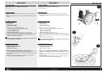
Anweisungen für das Abmontieren des Reifens (siehe Abb. 1 Seite 4)
» Den Blockierknopf im Gegenuhrzeigersinn drehen, um den Arm zu entblocken
» Das Kommandopedal (26) drücken, um die Tragsäule zu heben.
» Das Pedal (25) drücken, um die Greifer auf die Innenblockierung des Felgens einzustellen (im Falle
der Innenblockierung braucht dieser Vorgang nicht durchgeführt zu werden).
» Das Rad auf den Selbstzentrierer legen, wofür leichter Druck auf den Felgen ausgeübt wird; das
Kommandopedal (25) drücken (und sofort wieder loslassen), um das Rad zu blockieren.
» Den Radwulst mit dem dafür vorgesehenen Pinsel einfetten (siehe Zubehörschachtel).
» Kurz das Pedal (26) drücken, um die Tragsäule herunterzulassen.
» Den Drehkopf (2) in Felgennähe bringen und damit die Rolle (4) und die Oberfläche am Rand
berühren; durch Drehen des Blockierknopfs (3) im Uhrzeigersinn bewirkt man das automatische
Abrücken vom Felgen in waagrechter und senkrechter Stellung und die Blockierung der Abdrückkralle.
» Den Wulst mit der entsprechenden Wulstheberstange hochdrücken (Abb. 32) und auf den Drehkopfkeil
legen (2);
» Den Selbstzentrierer durch Pedaldruck (23) bis zur vollständigen Herauslösung des Wulstes aus
dem Felgen kreisen lassen.
Bei der Arbeit große Vorsicht walten lassen und während der Drehphase des
Selbstzentrierers nicht die Finger zwischen Reifen und Felgen bringen
» Die Tragsäule durch Betätigung des Pedals (26) hochheben und die Luftkammer herausziehen (nicht
notwendig bei schlauchlosen Reifen)
» Die gleichen Handgriffe für das Abdrücken des zweiten Reifenwulstes durchführen
FELGEN IN ALLUMINIUM UND LEICHTLEGIERUNG (Abb.33)
Für das Abnehmen der Reifen von Alluminium- oder Leichtlegierungsfelgen die Anweisungen für das
‘normale’ Reifenabnehmen befolgen bis zum Hochheben des 1. Reifenwulstes (siehe oben) und
dannach:
» durch entsprechende Druckausübung die untere Rolle an den Reifen annähern
» die Wulstheberstange entfernen (um Beschädi-gungen am äußeren Felgenrand zu vermeiden)
» die Rolle im Uhrzeigersinn kreisen lassen, bis der erste Wulst vollständig herausgetreten ist.
» den 2. Wulst auf den Drehkopfkeil heben
» die untere Rolle (wie oben) an den Reifen annähern die Wulstheberstange entfernen (um
Beschädigungen am äußeren Felgenrand zu vermeiden)
» die Rolle im Uhrzeigersinn bis zum vollständigen Heraustreten des Reifenwulsts kreisen lassen
MONTAGE
(siehe Abb. 1 Seite 4)
» Die Reifenwülste einschmieren
» Den Reifen auf den Felgen auflegen
» Die Tragsäule durch kurzen Druck auf das Pedal (26) herunterlassen
» Den Drehkopf in Arbeitsstellung bringen
» Den Wulst an den Rand des Drehkopfs (2) und unter den Keil (Abb. 34) legen;
» Den Selbstzentrierer durch Druck auf das Umkehrpedal (23) zum Drehen bringen und darauf achten,
daß der Wulst in die Mittelrille des Felgens hineingleitet, um so die Zerfaserung des Wulstes zu
vermeiden. (bei diesem Vorgang ist es ratsam, durch Drücken mit den Händen auf den Reifen
nachzuhelfen).
» Die Tragsäule durch Druck auf das Pedal (26) hochheben.
» Den Felgen mit dem Loch für die Luftkammer in circa 90 Grad von dem Drehkopf entfernt positionieren;
die Luftkammer einführen
» die Anfangsoperationen wiederholen (siehe oben), um den zweiten Wulst einzuwulsten
» Das Pedal (26) drücken, um den die Tragsäule zu heben und dann das Pedal (25), um den Felgen
freizulegen.
FELGEN IN ALLUMINIUM UND IN LEICHTLEGIERUNG (siehe Abb.35)
Zur Reifenmontage auf Alluminiumfelgen oder Felgen in Leichtlegierung sich an die Anweisungen für
die “normale” Montage halten (siehe oben)
Achtung: Sollte sich aufgrund des heruntergelassenen Reifens (45/30/35) die Montage des 2.
Reifenwulstes als schwierig erweisen, gehen Sie bitte wie folgt vor:
» die obere Rolle seitlich dem Reifen nähern (wie in Abb. 35)
» die Selbstzentriererplatte kreisen lassen, bis die Montage zu Ende geführt ist
Um den Felgen zu entblocken:
» die Drehsäule durch Druck auf das Pedal (26) “hochheben”
» die Blockierschraube losschrauben (und dann entfernen) und so den Felgen freilegen
DESMONTAJE
Instrucciones para las operaciones de desmontaje del neumático (véase la fig. 1 de pág. 4)
» Gire en sentido antihorario la palanca de bloqueo para desbloquear el brazo.
» Apriete el pedal (26) para elevar la columna.
» Apriete el pedal (25) para predisponer las mordazas al bloqueo interior de la llanta (en caso de
bloqueo exterior esta operación debe evitarse) .
» Ponga la rueda sobre el autocentrado actuando una presión muy leve sobre la llanta; apriete du-
rante poco el pedal (25) para bloquearla.
» Lubrifique el talón con la grasa utilizando el pincel de equipo (vea la caja de los accesorios).
» Apriete durante poco el pedal (26) para bajar la columna.
» Lleve la torre (2) acerca de la llanta y haga tocar el rodillo (4) y la superficie con el borde: girando la
palanca de bloqueo en sentido antihorario obtendrá la separación automática horizontal y vertical
de la torre y el bloqueo del brazo.
» Levante el talón con la palanca apropiada (fig.32) y póngalo sobre la lengüeta de la torre (2).
» Gire el autocentrado apretando el pedal (23) hasta la salida del talón de la llanta.
Actúe con cuidado evitando introducir los dedos entre neumático y llanta, durante las
fases de rotación del autocentrado.
» Levante la columna apretando el pedal (26) y extraiga la cámara neumática (con los Tubeless no es
necesario).
» Repita las mismas operaciones para la salida del segundo talón.
LLANTAS DE ALUMINIO Y ALEACION LIGERA (fig.33)
Para desmontar los neumáticos instalados sobre las llantas de aluminio o de aleación ligera, siga las
instrucciones “normales” de desmontaje hasta el levantamiento del I° talón (véase más arriba). Por
consiguiente:
» Acerque el rodillo inferior al neumático efectuando una presión adecuada.
» Quite la palanca levanta-talones (para evitar de dañar el borde exterior de la llanta).
» Gire en sentido antihorario hasta el desmontaje del primer talón.
» Elevar el II° talón sobre la lengüeta de la torre.
» Acerque el rodillo inferior al neumático como arriba.
» Quite la palanca (para no dañar el borde exterior de la llanta).
» Gire en sentido horario hasta el desmontaje completo.
MONTAJE
(véase la fig. 1 de pág. 4)
» Lubrifique los talones del neumático.
» Ponga el neumático sobre la llanta.
» Baje la columna apretando durante poco el pedal 26.
» Lleve la torre en posición de trabajo.
» Ponga el talón sobre el borde de la torre (2) y debajo de la lengüeta (fig.34).
» Gire el autocentrado apretando el pedal invertidor (23) teniendo cuidado para hacer entrar el talón
en la ranura central de la llanta, para eliminar deformaciones del talón mismo. N.B: Para favorecer
esta operación se aconseja presionar sobre el neumático con ambas manos.
» Elevar la columna apretando el pedal (26).
» Coloque la llanta con el orificio para la válvula de la cámara neumática a unos 90° de la torre; luego
introduzca la cámara neumática.
» Repita las operaciones iniciales (vea arriba) para hacer entrar el segundo talón.
» Apriete el pedal (26) para alzar la columna y luego el pedal (25) para desbloquear la llanta.
LLANTAS DE ALUMINIO Y DE ALEACION LIGERA (ved. Fig.35)
Para montar los neumáticos sobre las llantas de aluminio o de aleación ligera, siga las instrucciones
previstas para el montaje “normal” (véase más arriba).
ATENCION: si a causa del neumático rebajado (45 / 40 /35) el montaje del II° talón resultara demasiado
dificultoso, actúe de la manera siguiente:
» Acerque el rodillo superior al lado del neumático (como indica la fig. 35).
» Gire el plato del autocentrado hasta el montaje.
Para desbloquear la llanta:
» Eleve la columna apretando el pedal (26).
» Destornille (y luego quite) el tornillo de sujeción y libere la llanta.
DEMOUNTING
instructions for demounting tyres (see figure 1 on pg. 4)
» Turn the locking grip anti-clockwise to unlock the arm.
» Press pedal (26) to raise the column.
» Press pedal (25) to prepare the jaws for the internal locking of the rim (for external locking this
operation is not carried out).
» Put the wheel on the chuck pressing down lightly on the rim; press (and immediately release) pedal
(25) to lock it.
» Lubricate the bead with lubricant using the brush supplied (see accessories box).
» Press (and immediately release) pedal (26) to lower the column.
» Move the head (2) near to the rim so that the roller (4) touches the surface of the flange. Move the
locking grip clockwise to achieve the automatic horizontal and vertical distancing from the rim, as
well as locking the arm.
» Raise the bead with the special lever (fig. 32) and place it on the head tongue (2).
» Rotate the chuck by pressing the pedal (23) until the bead comes completely out of the rim.
Take care not to insert fingers between tyre and rim while the chuck is rotating.
» Raise the column by pressing pedal (26) and remove the inner-tube (this is not necessary with
tubeless tyres).
» Repeat the operation to remove the second bead.
ALUMINIUM AND LIGHT ALLOY RIMS (FIG.33)
To demount tyres fitted to aluminium or light alloy rims, follow the normal demounting procedure until
the raising of the first bead (See above). Then:
» Move the lower roller to the tyre exerting suitable pressure.
» Remove the bead lifting lever (to avoid damaging the outside flange of the rim)
» Rotate clockwise until the first bead is completely un-mounted
» Lift the second bead onto the tongue of the tool.
» Move the lower roller to the tyre, as above.
» Remove the lever (to avoid damaging the outside flange of the rim).
» Rotate clockwise until the demounting is complete.
MOUNTING
(see figure 1 on pg. 4)
» Lubricate the tyre bead.
» Rest the tyre on the rim.
» Lower the column pressing (and immediately releasing) pedal (26.)
» Move the head into its working position
» Rest the bead on the edge of the head (2) and under the tongue as in fig. 34.
» Rotate the chuck by pressing the invertor pedal (23) making sure that the bead enters the central
channel of the rim so as to avoid straining the bead (N.B. to help this process it is advisable to press
the tyre with the hands).
» Raise the column by pressing pedal (26).
» Position the rim with the hole for the inner-tube at about 90° to the head. Insert the inner-tube.
» Repeat the initial operations (see above) to insert the second bead.
» Press pedal (26) to raise the column and then press pedal (25) to release the rim.
ALUMINIUM AND LIGHT ALLOY RIMS (see Fig.35)
To mount tyres onto aluminium or light alloy rims, follow the normal mounting procedure (see above).
Warning: When mounting low-profile tyres (45/40/35) it may be difficult to mount the second bead. In
this case, proceed as follows:
» Move the upper roller to the side of the tyre (as in fig. 35).
» Rotate the chuck plate until mounting is complete.
To unlock the wheel:
» Raise the column by pressing the pedal (26).
» Unscrew (and remove) the fixing bolts and free the rim.
Содержание FALCO AF1718
Страница 36: ...N 102180 Rev 6 COMBINED FALCOAF 1718 AF1720 IT RACING ITE RACING...
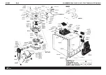
Страница 37: ...N 102583 Rev 6 COMBINED FALCOAF 1718 AF1720 IT RACING ITE RACING...
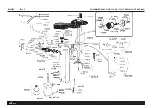
Страница 38: ...N 101051 Rev 5 COMBINED FALCOAF 1718 AF1720 IT RACING ITE RACING...
Страница 39: ...N 101065 Rev 5 COMBINED FALCOAF 1718 AF1720 IT RACING ITE RACING...
Страница 40: ...N 101045 Rev 13 OPTIONAL...
Страница 41: ...N 102181 Rev 4 COMBINED FALCOAF 1718 AF1720 IT RACING ITE RACING...
Страница 42: ...N 101074 Rev 5 COMBINED FALCOAF 1718 AF1720 IT RACING ITE RACING...
Страница 43: ...N 101289 Rev 4 COMBINED FALCOAF 1718 AF1720 IT RACING ITE RACING...
Страница 44: ...N 101122 Rev 0 COMBINED FALCOAF 1718 AF1720 IT RACING ITE RACING...
Страница 45: ...N 101120 Rev 7 COMBINED FALCOAF 1718 AF1720 IT RACING ITE RACING...
Страница 46: ...N 101519 Rev 2 COMBINED FALCOAF 1718 AF1720 IT RACING ITE RACING...
Страница 47: ...N 100933 01 Rev 0 COMBINED FALCOAF 1718 AF1720 IT RACING ITE RACING...
Страница 48: ...N 100933 02 Rev 0 COMBINED FALCOAF 1718 AF1720 IT RACING ITE RACING...
Страница 49: ...N 100933 03 Rev 0 COMBINED FALCOAF 1718 AF1720 IT RACING ITE RACING...
Страница 50: ...N 100933 04 Rev 0 COMBINED FALCOAF 1718 AF1720 IT RACING ITE RACING...
Страница 51: ...N 101125 01 Rev 0 COMBINED FALCOAF 1718 AF1720 IT RACING ITE RACING...
Страница 52: ...N 101125 02 Rev 0 COMBINED FALCOAF 1718 AF1720 IT RACING ITE RACING...
Страница 53: ...N 101125 03 Rev 0 COMBINED FALCOAF 1718 AF1720 IT RACING ITE RACING...

