MAN-059
8 FEB 2017
29
15.
Control System Setup
1.
Ensure the battery is fully charged and in good working condition before connecting the SIBS® controller.
2.
With the vehicle engine running, twist and release the red E-stop button to release the brakes - the system will
automatically detect the correct brake release pressure during its first release.
3.
Activate all connected interlocks and check function:
a.
To activate the door interlock
–
open and close a vehicle door.
b.
To activate the seat belt interlock
–
connect and disconnect the driver’s seatbelt.
c.
To activate the stall interlock
–
switch the ignition off, wait for 5 seconds, then start the engine, run for 10 seconds
and then switch the engine off again.
d.
The corresponding warning light on the control unit should display when each interlock is activated (note:
interlock warning lights are only displayed when ignition is on).
4.
Set the HSI speed threshold:
a.
After releasing the brake for the first time the green HSI light will begin flashing
–
this indicates the HSI speed
threshold needs to be set.
b.
The HSI system overrides the door, stall and seatbelt interlocks when the vehicle is travelling at speeds above the
HSI threshold
–
this is designed to prevent unintended brake application at high speeds.
c.
Start the engine, release the brakes and accelerate the vehicle up to the desired HSI threshold speed (ABT
recommends 40 km/h).
d.
While maintaining this speed, press and hold the grey button on the control unit for 3 seconds
–
the control unit
will beep twice to confirm the speed has been accepted.
e.
If HSI is not required, simply complete the above procedure with the vehicle is stationary.
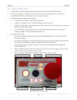
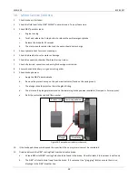
Figure 19: SIBS® control unit warning lights
Stall interlock active
Seatbelt interlock active
Door interlock active
Highway speed isolation status
Low fluid level in pump reservoir
Fault indicator
Содержание Fuso Canter
Страница 1: ...SIBS 4 WORKSHOP MANUAL FUSO CANTER...
Страница 7: ...MAN 059 8 FEB 2017 7 6 Exploded Views Parts Lists Differential Brake Assembly...
Страница 10: ...MAN 059 8 FEB 2017 10 7 Wiring Diagram 12V TO SPEED SIGNAL TO IGNITION TO OIL PRESSURE TO SEAT BELT 12V...
Страница 11: ...MAN 059 8 FEB 2017 11 10A FUSE 30A FUSE 12V POWER...
Страница 12: ...MAN 059 8 FEB 2017 12 8 Wiring Diagram 24V TO SPEED SIGNAL TO IGNITION TO OIL PRESSURE TO SEAT BELT...
Страница 13: ...MAN 059 8 FEB 2017 13...
Страница 14: ...MAN 059 8 FEB 2017 14 9 Pump Hardware Parts List 12V...
Страница 16: ...MAN 059 8 FEB 2017 16 10 Pump Hardware Parts List 24V...


