MAN-059
8 FEB 2017
23
13.
Installation
–
Electrical System
1.
Isolate the vehicle battery.
2.
Do not test the control system functions until the system is fully installed as this may confuse the control unit while
learning
–
details on control unit setup can be found in section 15.
3.
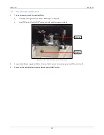
Mount the control unit to the dash:
a.
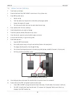
Mount the SIBS® control unit on the dash above the centre console using the provided bracket. Position so that
bracket is close to the driver and aligned with the vehicle axis. 4x holes will need to be drilled.
b.
For LH drive vehicles the control unit bracket can be reversed so that it is always facing the vehicle operator.
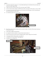
Figure 11: SIBS® 4 control unit mounted on dash.
4.
Fit the SIBS® cabin harness 18-7012:
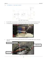
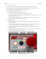
Figure 12: Control unit wiring.
a.
Connect cabin harness branch to the rear of the control unit by passing up through the dash. A hole will need to be
drilled in the dash to achieve this.
b.
It may be easier to route the cabin harness with 2 of the Deutsch connectors de-pinned.
i.
Locate the connectors for the battery power and relay, approximately 2 metres from the end of the
harness.
Control Box bracket
Centre removed to access
fasteners and wiring
Control Box bracket mounting bolts
Control Box harness with grommet attached
Control box harness passed through dash
Содержание Fuso Canter
Страница 1: ...SIBS 4 WORKSHOP MANUAL FUSO CANTER...
Страница 7: ...MAN 059 8 FEB 2017 7 6 Exploded Views Parts Lists Differential Brake Assembly...
Страница 10: ...MAN 059 8 FEB 2017 10 7 Wiring Diagram 12V TO SPEED SIGNAL TO IGNITION TO OIL PRESSURE TO SEAT BELT 12V...
Страница 11: ...MAN 059 8 FEB 2017 11 10A FUSE 30A FUSE 12V POWER...
Страница 12: ...MAN 059 8 FEB 2017 12 8 Wiring Diagram 24V TO SPEED SIGNAL TO IGNITION TO OIL PRESSURE TO SEAT BELT...
Страница 13: ...MAN 059 8 FEB 2017 13...
Страница 14: ...MAN 059 8 FEB 2017 14 9 Pump Hardware Parts List 12V...
Страница 16: ...MAN 059 8 FEB 2017 16 10 Pump Hardware Parts List 24V...


