MAN-059
8 FEB 2017
18
11.
Installation
–
Driveline Brake (Light - Medium Trucks)
1.
The SIBS® driveline brake is installed on the forward side of rear differential carrier.
2.
Drain and keep enough diff oil from the rear differential carrier to prevent spillage as the pinion bearing cage will be
removed for SIBS® brake installation.
3.
Remove drive shaft from rear yoke. The drive shaft may be removed completely if desired.
4.
Remove the yoke from the pinion shaft.
5.
Remove the pinion bearing cage and retain any shims for later use. Ensure no dirt ingress into the diff centre.
6.
Remove and keep the bearing rollers. Remove and discard pinion seal.
7.
The pinion bearing cage must be machined as per ABT drawing to suit the attachment of the SIBS® brake.
8.
Attach the modified pinion bearing cage to the diff centre as per Canter manual. Ensure all shims are reused. Do not
attach any mounting bolts at this stage.
9.
Attach the outer bearing roller and pull the pinion shaft forward to ensure it is positioned correctly.
10.
Attach the pinion seal to the bearing cage.
11.
Apply Loctite 515 between the bearing cage and the SIBS® inner brake housing. Note: in some cases a mounting adapter
is required between the bearing cage and the inner housing. If required apply Loctite 515 to both sides.
12.
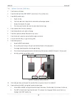
Attach the inner housing with the brake pads positioned to the top of the brake.
13.
Attach the mounting bolts and washers. Torque to 100Nm. Repeat 3 times over 5 minutes.
14.
Ensure the housing o-ring is attached to the outer brake housing.
15.
Ensure the brake pads are in position on the inner brake housing.
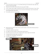
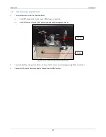
Figure 1: Diff centre with inner housing attached.
16.
Attach the V-seal to the yoke.
17.
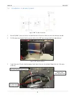
The preassembled outer housing should be attached to the yoke and rotor. Ensure brake pads are attached to the outer
housing.
Brake Pads
Mounting Bolts and washers
Pinion
Seal
Содержание Fuso Canter
Страница 1: ...SIBS 4 WORKSHOP MANUAL FUSO CANTER...
Страница 7: ...MAN 059 8 FEB 2017 7 6 Exploded Views Parts Lists Differential Brake Assembly...
Страница 10: ...MAN 059 8 FEB 2017 10 7 Wiring Diagram 12V TO SPEED SIGNAL TO IGNITION TO OIL PRESSURE TO SEAT BELT 12V...
Страница 11: ...MAN 059 8 FEB 2017 11 10A FUSE 30A FUSE 12V POWER...
Страница 12: ...MAN 059 8 FEB 2017 12 8 Wiring Diagram 24V TO SPEED SIGNAL TO IGNITION TO OIL PRESSURE TO SEAT BELT...
Страница 13: ...MAN 059 8 FEB 2017 13...
Страница 14: ...MAN 059 8 FEB 2017 14 9 Pump Hardware Parts List 12V...
Страница 16: ...MAN 059 8 FEB 2017 16 10 Pump Hardware Parts List 24V...


