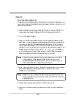
- 10 -
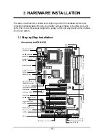
This section outlines how to install and configure your AV18 mainboard. Refer to the
following mainboard layout to help you identify various jumpers, connectors, slots, and
ports. Then follow these steps designed to guide you through a quick and correct installa-
tion of your system.
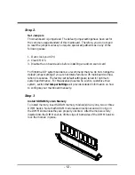
3.1 Step-by-Step Installation
Accessories Of AV18
3 HARDWARE INSTALLATION
VT82C693
9916CD TAIWAN
12BON6101
‘96
C
AWARD
All rights reserved
PCI/PNP 586
S/N 1997
KEYBOARD & MOUSE
USB PORT
COM 2
COM 1 PRINT
ISA 1
AV 18
AMR 1
PCI 5
PCI 4
PCI 3
PCI 2
PCI 1
AGP 1
DIMM 1
DIMM 2
ATX PWR
DIMM 3
FDC 1
1
IDE1
IDE2
1
1
PGA370
JP10
CD_IN
TAD I/O
AUX
1
JP11
1
JP12
1
VT82C686A
0006CF TAIWAN
1EK415111
FAN 2 1
FAN 3
1
FAN 1
1
JP 4
2
4
6
8
1
3
5
7
SPEAKER
POWER LED
HDLED
RST
EPMI
GLED
PWON
J 3
JP 5
EXT USB PORT
1
JP 6
1
JP 1
IR
1
JP 2
1
JP 7
2
4
6
8
1
3
5
7
Wake On Lan
J2
1
PS2 Keyboard/Mouse
Connectors
Two USB Connectors
Socket 370
Serial Port Connector
(COM2)
Serial Port Connector
(COM1)
Parallel Connector
VIA 694X Chipset
Line_In/Line_Out/Mic_In
GAME/MIDI Connectors
Onboard Audio
Connectors-JP10/JP11/JP12
AGP 2x/4x Slot
AMR Slot
ISA Slot
AC97 Audio CODEC
Five PCI Slots
Two USB Ports Header - JP5
Programmable Flash
EEPROM
IR Connector- JP1
EEPROM Block Lock- JP6
Wake On Lan Connector- J2
Front Panel Connectors- J3
CPU Clock Ratio Setting- JP4
Clear CMOS- JP2
ATX Power Connector
Floppy Connector
FAN 1
FAN 2
Two IDE Connectors
FAN 3
VIA 686A Chipset
System Clock Setting- JP7
RichTek
RT9231 CSAHK1
GD 75323D
HS49
GD 75323D
HS49
CA3757A ES
0005
9248CF 438


