background image

-32-

Model W1836 (For Machines Mfd. Since 04/15)

M

A

INTE

N

A

N

CE

MAINTENANCE

Cleaning the Model W1836 is relatively easy. Vacuum 

excess wood chips and sawdust, and wipe off the remain-

ing dust with a dry cloth. If any resin has built up, use a 

resin dissolving cleaner to remove it.

Remove any debris or oily substances from the inside of 

the spindle and quill.

Protect the unpainted cast iron lathe bed by wiping it 

clean after every use—this ensures moisture from wood 

dust does not remain on the bare metal surfaces. Keep 

your lathe bed rust-free with regular applications of 

quality lubricants.

Cleaning.&.Protecting

Regular periodic maintenance on your machine will 

ensure its optimum performance. Make a habit of 

inspecting your machine each time you use it. 

Check.for.the.following.conditions.and.repair.or.

replace.when.necessary:

  Loose mounting bolts.

  Worn switch.

  Worn or damaged cords and plugs.

  Damaged V-belt.

  Any other condition that could hamper the safe 

operation of this machine.

General

MAKE. SURE. that. your. machine. is.

unplugged.during.all.maintenance.pro-

cedures!.If.this.warning.is.ignored,.seri-

ous.personal.injury.may.occur.

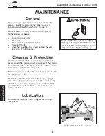
Figure.37..

Lubrication locations

.

Lubrication

Lubricate the locations shown in 

Figure 37 with light 

machine oil.

Содержание W1836

Страница 1: ...ATHE Phone 360 734 3482 Online Technical Support techsupport woodstockint com COPYRIGHT MAY 2015 BY WOODSTOCK INTERNATIONAL INC WARNING NO PORTION OF THIS MANUAL MAY BE REPRODUCED IN ANY SHAPE OR FORM...

Страница 2: ...g grinding tool integrity and the usage of personal protective equipment The manufacturer will not be held liable for injury or property damage from negligence improper training machine modifications...

Страница 3: ...eral 17 Operation Overview 18 Stock Inspection Requirements 18 Engaging Releasing Spindle Lock 19 Changing Spindle Speeds 20 Adjusting Tool Rest 22 Adjusting Tailstock Position 23 Installing Removing...

Страница 4: ...spirator 3 Only plug power cord into a grounded outlet 4 Only use this machine to collect wood dust chips never use to collect glass metal liquids asbestos silica animal parts biohazards burning mater...

Страница 5: ...ull Load Current Rating 7 4A Minimum Circuit Size 15A Connection Type Cord Plug Power Cord Included Yes Power Cord Length 6 ft Power Cord Gauge 18 AWG Plug Included Yes Included Plug Type 5 15 Switch...

Страница 6: ...Cast Iron Headstock Cast Iron Tailstock Cast Iron Paint Type Finish Enamel Other Related Information Bed Width 4 3 8 in Faceplate Size 3 in Other Country of Origin China Warranty 2 Years Approximate A...

Страница 7: ...ndle Lock Knob E Headstock F Faceplate G Work Lamp H Digital Readout I Tool Rest J Tool Rest Holder K Tailstock Lock Lever L Live Center M Quill N Quill Lock Handle O Tailstock P Quill Handwheel Q Too...

Страница 8: ...ndle within current belt position speed range Tool Rest Provides a stable resting position for turning tools Tool Rest Lock Handle Locks tool rest in position relative to tool rest base Tool Rest Lock...

Страница 9: ...or alcohol when tired or when distracted ELECTRICAL EQUIPMENT INJURY RISKS You can be shocked burned or killed by touching live electrical components or improperly grounded machinery To reduce this r...

Страница 10: ...ce accidental contact with moving parts or flying debris make sure they are properly installed undamaged and working correctly FORCING MACHINERY Do not force machine It will do the job safer and bette...

Страница 11: ...it through its entire range of motion EYE FACE PROTECTION Always wear a face shield and safety glasses when operating lathe PROPER APPAREL Do not wear gloves necktie or loose clothing Keep keep long h...

Страница 12: ...nts Circuit Type 110V 120V 60 Hz Single Phase Circuit Size 15 Amps Plug Receptacle NEMA 5 15 Full Load Current Rating The full load current rating is the amperage a machine draws at 100 of the rated o...

Страница 13: ...s properly grounded If you ever notice that a cord or plug is damaged or worn disconnect it from power and immediately replace it with a new one Grounding Prong Neutral Hot 5 15 PLUG GROUNDED 5 15 REC...

Страница 14: ...nventory them Note If you can t find an item on this list check the mounting location on the machine or examine the packaging materials carefully Occasionally we pre install certain components for saf...

Страница 15: ...talled where chil dren are present Cleaning Machine The table and other unpainted parts of your machine are coated with a waxy grease that protects them from corrosion during shipment Clean this greas...

Страница 16: ...g holes that allow it to be fastened to a workbench or other mounting surface to prevent it from moving during operation and causing accidental injury or damage The rubber feet on this machine must be...

Страница 17: ...le to quill handwheel with 1 M6 1 X 10 7 X 44 shoulder bolt see Figure 10 Assembly Figure 10 Quill handwheel handle installed Quill Handwheel Handle Figure 11 Tool holder and cord holder installed Too...

Страница 18: ...to low see Figure 12 4 Connect machine to power source 5 Verify machine is operating correctly by turning machine ON with paddle switch then rotating variable speed dial clockwise to start spindle ro...

Страница 19: ...achine The overview below provides the novice machine operator with a basic understanding of how the machine is used during operation so the machine controls components discussed later in this manual...

Страница 20: ...t injures Only turn concentric workpieces The purpose of this overview is to provide the novice machine operator with a basic understanding of how the machine is used during operation so the machine c...

Страница 21: ...e lock to the Run position The spindle lock knob will have a noticeable gap between the bottom of it and the headstock when set properly see Figure 13 Alternately you can set the spindle lock knob so...

Страница 22: ...ce breaking loose or being thrown from lathe at a high rate of speed causing fatal or severe impact injuries Diameter of Workpiece Roughing RPM General Cutting RPM Finishing RPM Under 2 1520 3000 3000...

Страница 23: ...when stopping the lathe This will prevent unexpected rotational speeds or surprises the next time the lathe is started Figure 17 Proper belt deflection Pulley Deflection Pulley 1 2 5 Push down on belt...

Страница 24: ...lock tool rest base in place If release lever will not lock tool rest base onto bed either too loose or too tight then loosen or tighten lock nut located on underside of tool rest base in small incre...

Страница 25: ...bed To position tailstock along bed do these steps 1 Loosen lock lever and slide tailstock to desired position see Figure 21 2 Re engage lock lever If lock lever does not firmly lock tailstock down on...

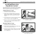
Страница 26: ...3 Insert tapered end of center into spindle and push it in with a quick firm motion see Figure 22 4 Make sure center is securely installed by attempting to pull it out by hand a properly installed cen...

Страница 27: ...installed center will not pull out easily 5 Tighten quill lock handle Installing Tailstock Center Removing Tailstock Center Turn quill handwheel counterclockwise until tailstock quill fully retracts c...

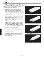
Страница 28: ...flat double ground with one side higher than the other usually at an angle of 20 40 Figure 27 shows an example of a skew chisel Scrapers Mainly used where access for other tools is limited such as hol...

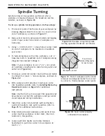
Страница 29: ...er into center mark with wood mallet to embed it at least 1 4 into workpiece as shown in Figure 32 6 With workpiece still attached insert spur center into headstock spindle refer to Installing Removin...

Страница 30: ...ques for each turning tool you use If you are unsure about how to use any individual tool read books or magazines about lathe techniques and seek training from experienced and knowledgeable lathe user...

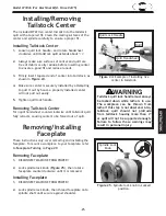
Страница 31: ...ock spindle as described in Removing Installing Faceplate on Page 25 If wood screws cannot be placed in workpiece faceplate can be mounted to a backing block attached to the workpiece as described bel...

Страница 32: ...your hands into moving workpiece and cause serious injury Never wrap sandpaper or finishing materials completely around the workpiece Note Whenever sanding or finishing move the tool rest holder out o...

Страница 33: ...larger bench top machines The table has a butcher block finish and measures 14 x 40 x 11 4 thick The wide A frame stand has a 700 lb capacity and measures 33 high Includes stand frame and top The D45...

Страница 34: ...r lathe bed rust free with regular applications of quality lubricants Cleaning Protecting Regular periodic maintenance on your machine will ensure its optimum performance Make a habit of inspecting yo...

Страница 35: ...ock handle see Figure 38 3 Press belt tension lever down then tighten belt tension lock handle 4 Press belt with moderate pressure in center to check tension Belt is correctly tensioned when there is...

Страница 36: ...hese steps 1 DISCONNECT MACHINE FROM POWER 2 Gain access to motor brushes by following Steps 1 3 in Replacing Belt 3 Unscrew brush cap with flat head screwdriver 4 Carefully remove brush from motor se...

Страница 37: ...6 Test replace 7 Test replace 8 Test repair replace Machine stalls or is underpowered 1 Machine undersized for task 2 Workpiece material not suitable for machine 3 Feed rate cutting speed too fast 4 B...

Страница 38: ...indle bearings are worn 1 Remount workpiece making sure that centers are embedded in true center of workpiece 2 Stop lathe and fix interference problem 3 Check clamp levers and tighten if necessary 4...

Страница 39: ...k all wires disconnected or connected during any wiring task to ensure tight connections WIRE COMPONENT DAMAGE Damaged wires or components increase the risk of serious personal injury fire or machine...

Страница 40: ...ent Connections Figure 44 Electrical box wiring Figure 43 Digital readout and RPM sensor wiring Figure 42 Electrical component locations Figure 45 Motor plate RPM Sensor Digital Readout Digital Readou...

Страница 41: ...aker RU L2 6A 50VDC Transformer DZ 236A1 Electrical Box Viewed from Bottom Lathe Headstock RPM SENSOR DRO P0 0022 02 Digital Readout Viewed from Behind KEDU HY18 STOP Read Page 37 Before Wiring Wiring...

Страница 42: ...20 21 22 23 25 3 27 28 29 29 30 31 31 31 32 32 32 33 33 33 34 34 34 35 36 37 38 39 40 41 42 45 46 47 48 49 50 51 51 52 52 53 54 55 55 57 58 59 60 61 61 62 63 64 65 66 67 68 69 70 71 72 73 74 75 76 77...

Страница 43: ...X1836025 POINTER 79 X1836079 SWITCH BOX 27 X1836027 WORK LIGHT 80 X1836080 STRAIN RELIEF PG7 TYPE 3 28 X1836028 TOOL REST 148L POST 16 X 75 81 X1836081 STRAIN RELIEF PG9 TYPE 3 29 X1836029 EXT RETAIN...

Страница 44: ...lock turn counterclockwise To lock push and turn clockwise WARNING ENTANGLEMENT READ and UNDERSTAND MANUAL to avoid serious WARNING WARNING EYE FACE LUNG INJURY HAZARD ACCIDENTAL INJURY HAZARD Disconn...

Страница 45: ...Model W1836 For Machines Mfd Since 04 15...

Страница 46: ...tape along edges please do not staple Fold along dotted lIne Fold along dotted lIne Woodstock international inc p o box 2309 bellingham Wa 98227 2309 place stamp Here...

Страница 47: ...he scope of Woodstock International Inc s warranty then the original owner must bear the cost of storing and returning the product This is Woodstock International Inc s sole written warranty and any a...

Страница 48: ...High Quality Machines and Tools Woodstock International Inc carries thousands of products designed to meet the needs of today s woodworkers and metalworkers Ask your dealer about these fine products...

Отзывы: